# RDS-Setup-Guide--B-Sample--08FEB2023
 by 
---
Unboxing 📦
# Unboxing
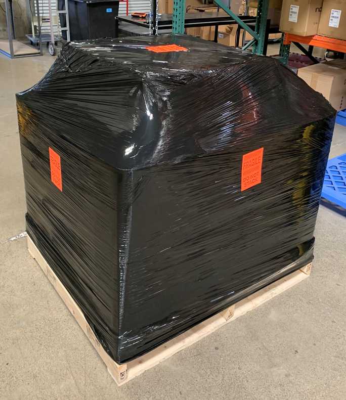
RDS Solution should arrive as shown:
## Master Carton
---
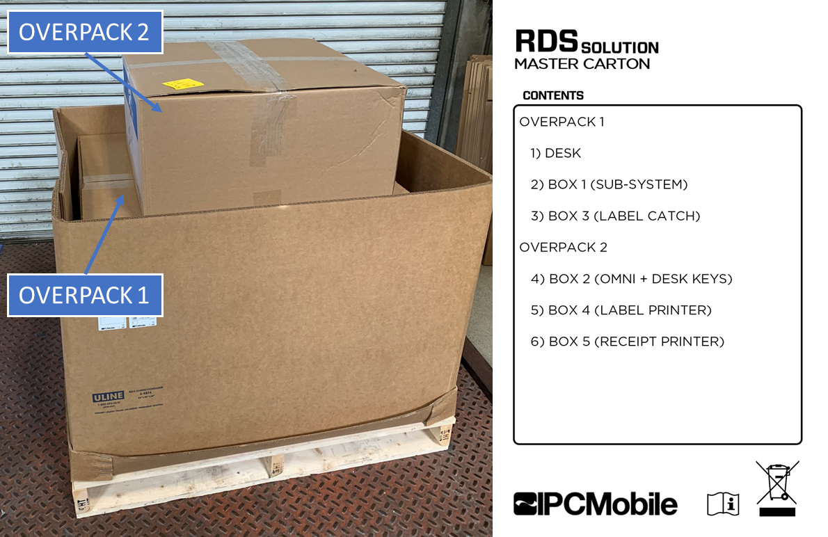
Removing the shrink wrap will reveal the overpack boxes underneath:
## Overpack
---
### Packaged Contents:
#### OVERPACK 1
- `RDS DESK`
- `BOX 1 (SUB-SYSTEM)`
- `BOX 3 (LABEL CATCH)`
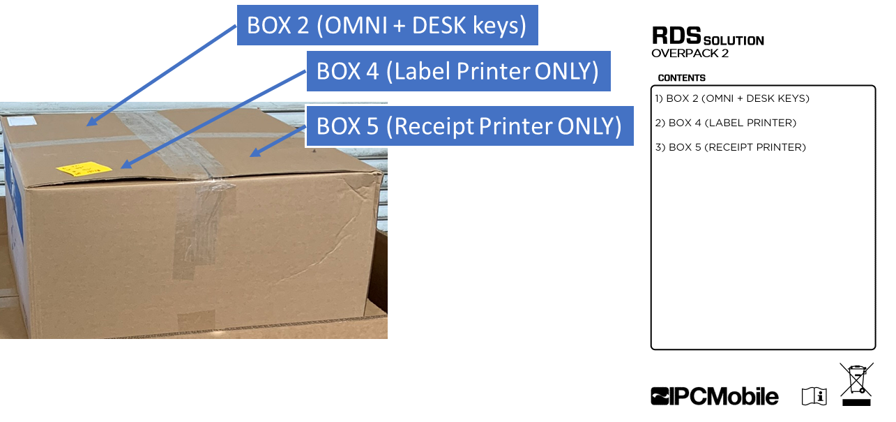
#### OVERPACK 2
- `BOX 2 (OMNI DEVICE)`
- `BOX 4 (LABEL PRINTER)`
- `BOX 5 (RECEIPT PRINTER)`
---
## Unboxing OVERPACK 1
1) Keep box orientated as packaged on pallete skid. Opening up the top will reveal contents within:
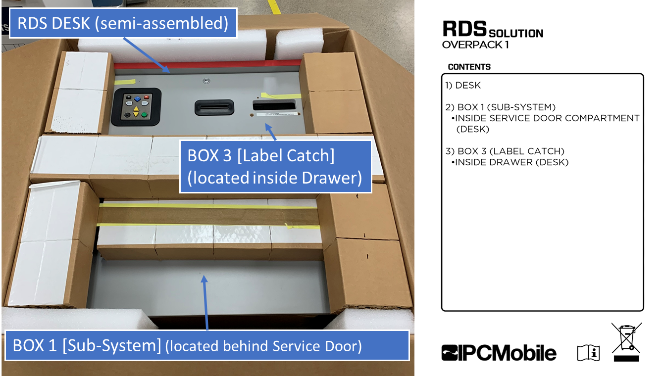
>**Note**
>`BOX 1` is located in the area behind the Service Door and `BOX 3` is located within the Drawer of `RDS DESK`.
2) Remove upper packaging contents to gain access to `RDS DESK`.
3) Remove `BOX 1` and `BOX 3` from their respective areas nested within `RDS DESK`. [^1]
4) Remove `RDS DESK` and place upright onto its feet.
---
## Unboxing OVERPACK 2
1) Remove contents from packaging:
---
## Unboxing BOX 1
1) Remove contents from packaging:
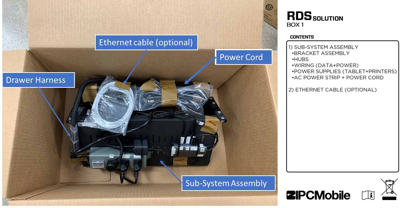
>**Note**
>Take care to remove all temporary tape and poly bags used to secure contents during shipping --> Labeled "REMOVE"
---
## Unboxing BOX 2
1) Remove contents from packaging:

---
## Unbox remaining items:
1) Unbox contents from `BOX 3` (Label Catch) SEE [Unboxing OVERPACK 1](#unboxing-overpack-1)
2) Unbox contents from `BOX 4` (Label Printer) SEE [Unboxing OVERPACK 2](#unboxing-overpack-2)
3) Unbox contents from `BOX 5` (Receipt Printer) SEE [Unboxing OVERPACK 2](#unboxing-overpack-2)
Installation 🔧
# Installation
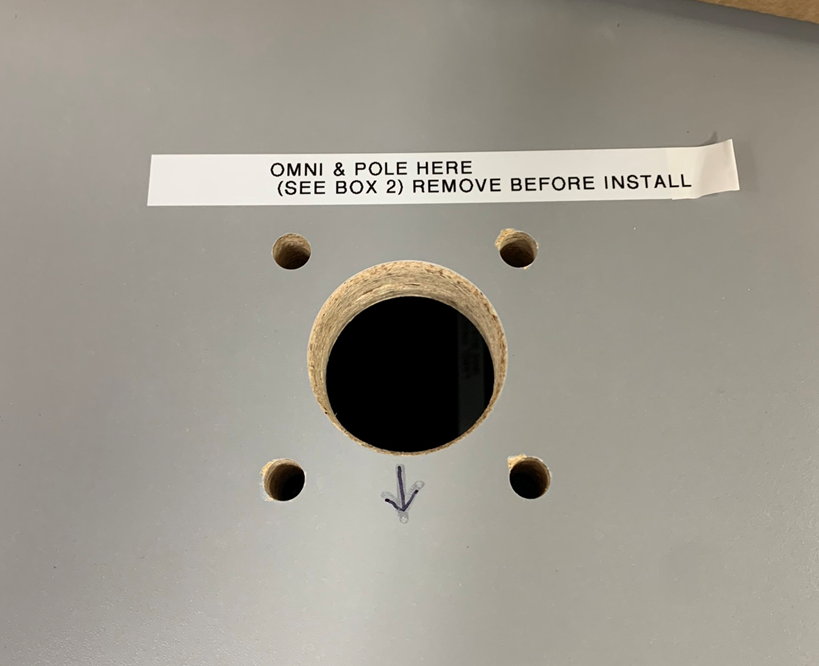
## Step 1. Install Omni + Pole Mount Assembly onto Desk
1) Note install location for `OMNI + POLE`. Remove temporary label.
>
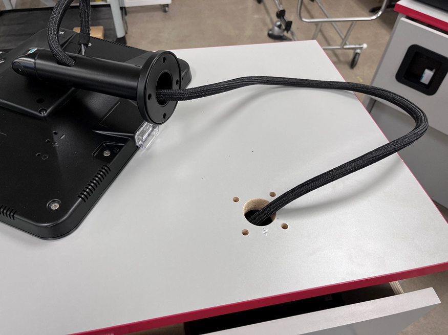
2) Route `OMNI` cable harness thru the large hole in the `RDS DESK` countertop.
>
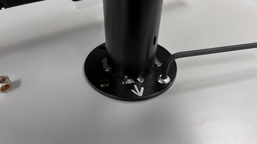
3) Align the arrows on the `RDS DESK` countertop and the arrow under the Pole bolt cover, facing the same direction, and place the `OMNI + POLE` over the four (4) holes in the `RDS DESK` countertop.
>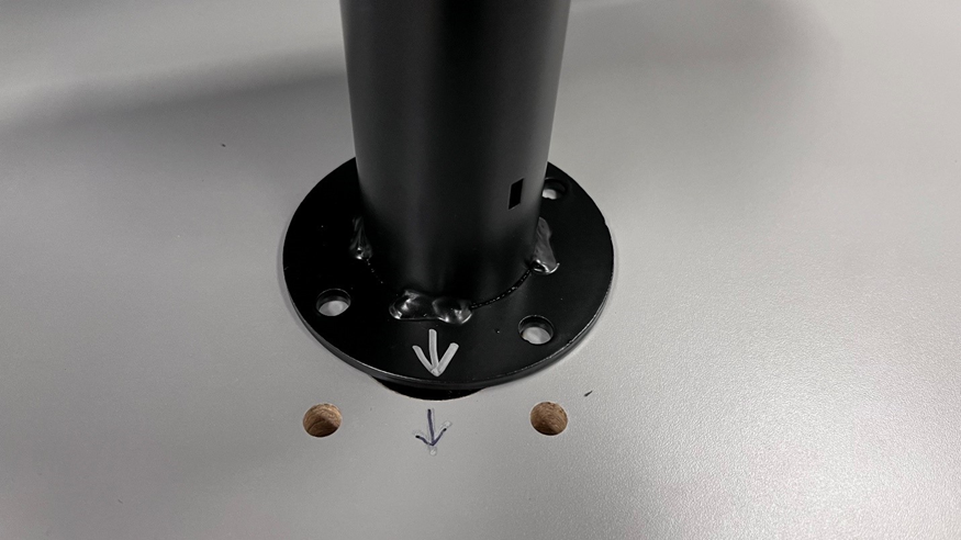
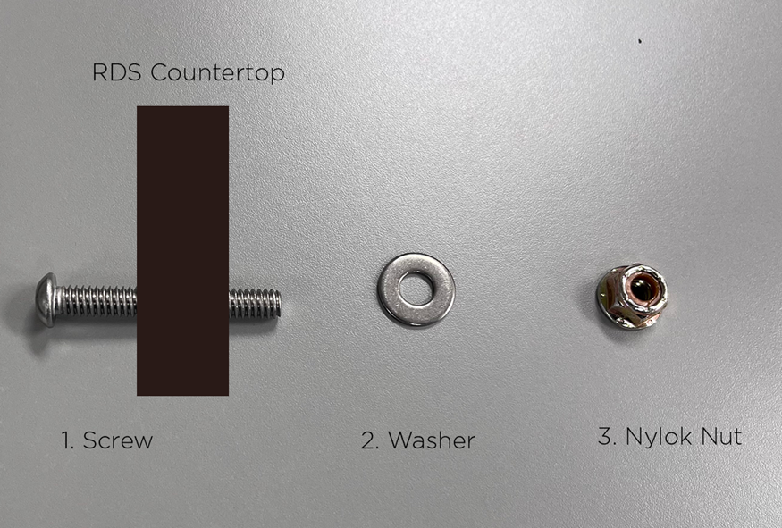
4) Place a screw thru the `POLE` and `RDS DESK` Countertop as shown. The nut and washer will be installed on the underside. Loosely tighten bolt assembly using a 5/32” allen key (supplied) and 7/16” wrench.
>
>
5) Repeat Step 4 for the remaining screws.
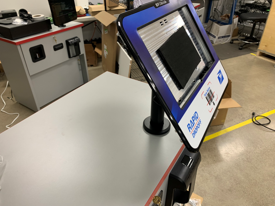
6) Ensure that the `OMNI` is facing rearward at full rotation in either/both directions by rotating until the Omni stops.
7) Once all screws and nuts/washers are installed, tighten all four (4) bolts to secure `OMNI + POLE` mount to `RDS DESK` countertop.
>
---
## Step 2. Install Sub-System + Bracket Assembly onto Desk
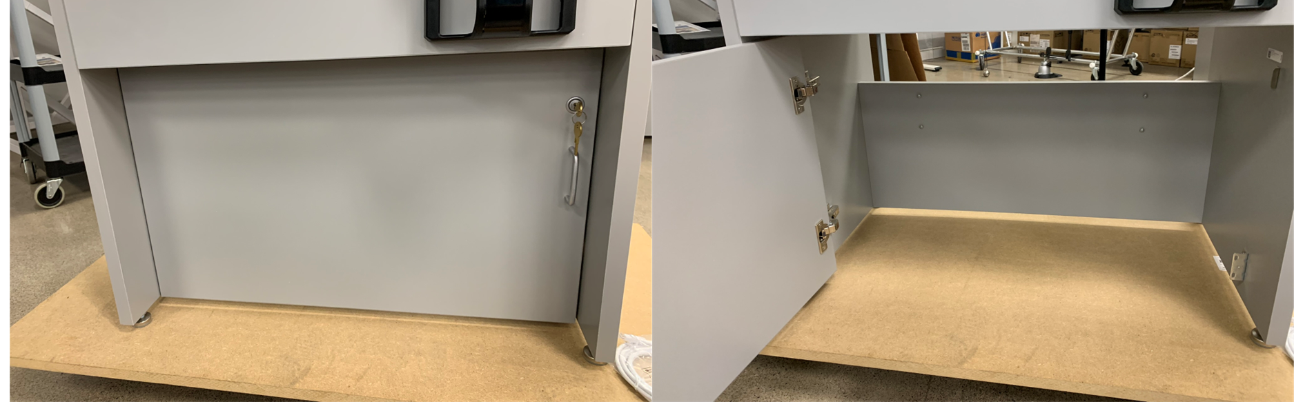
1) Open lower `Service Door`.
>
2) Note install location for `SUB-SYSTEM + BRACKET`.
>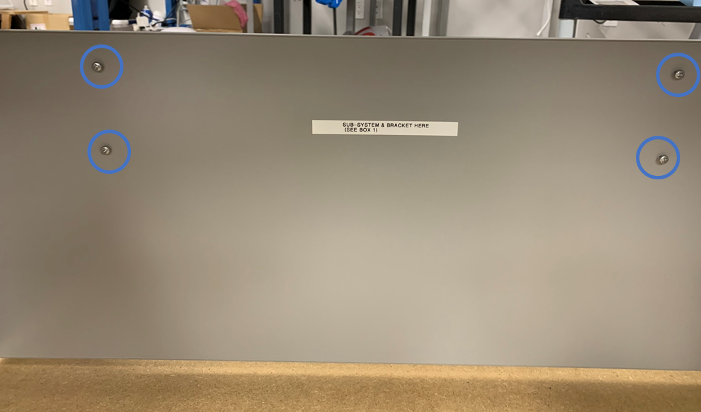
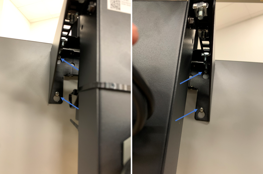
3) Place `SUB-SYSTEM + BRACKET` onto the 4 pre-installed screws.
>
4) Tighten the 4 screws to secure `SUB-SYSTEM + BRACKET` to `RDS DESK`.
>
---
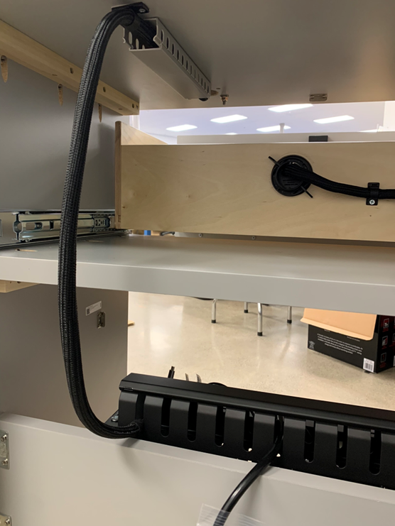
## Step 3. Route Omni Harness
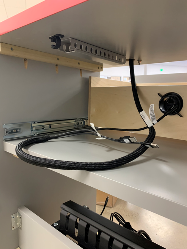
1) Extend `Drawer` fully open to gain access to underside of Desk countertop.
>
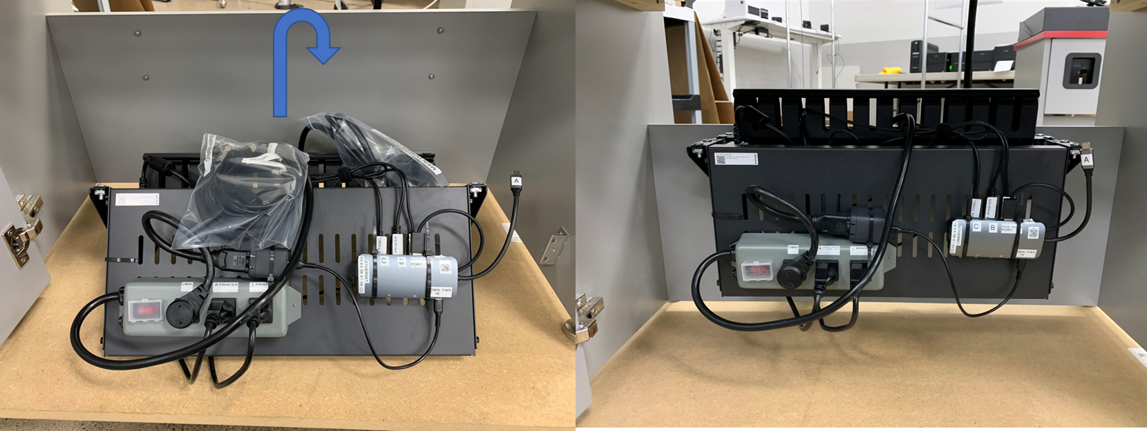
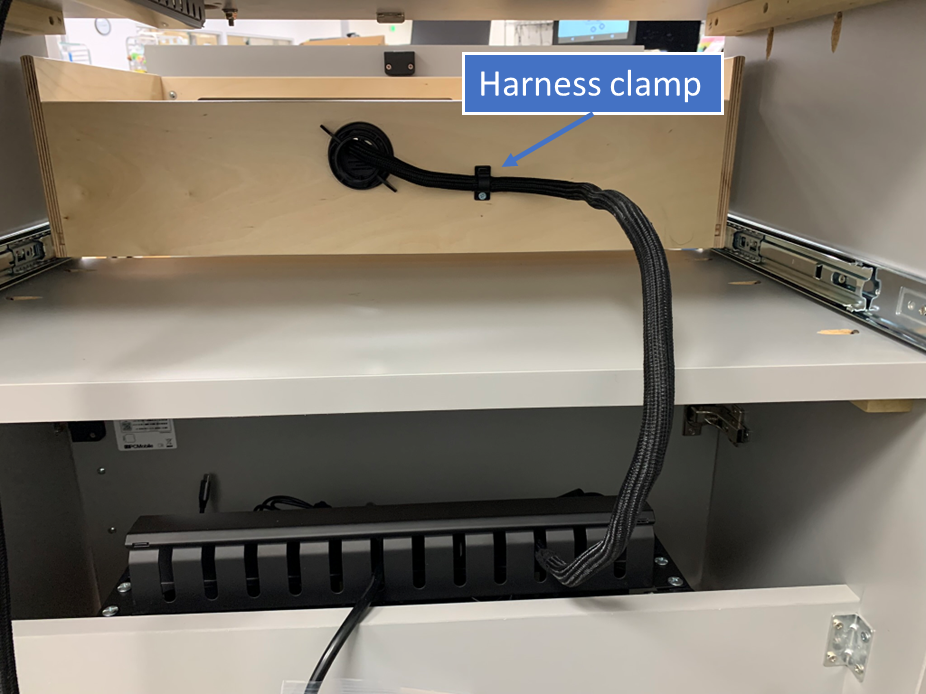
2) From the back side, remove cable duct `cap` and route `OMNI Harness` accordingly.
>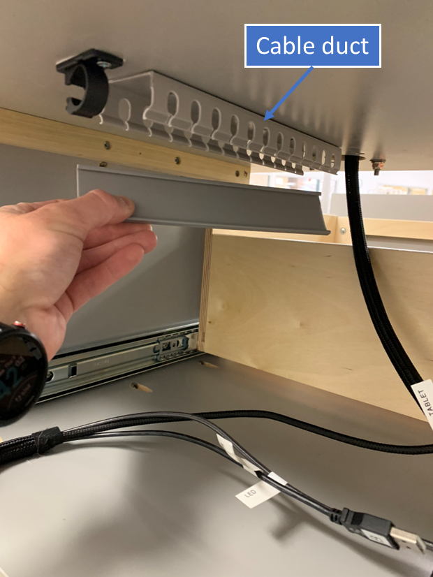
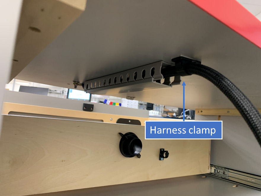
3) Reinstall cable duct `cap` and secure `OMNI Harness` by latching the `harness clamp`.
>
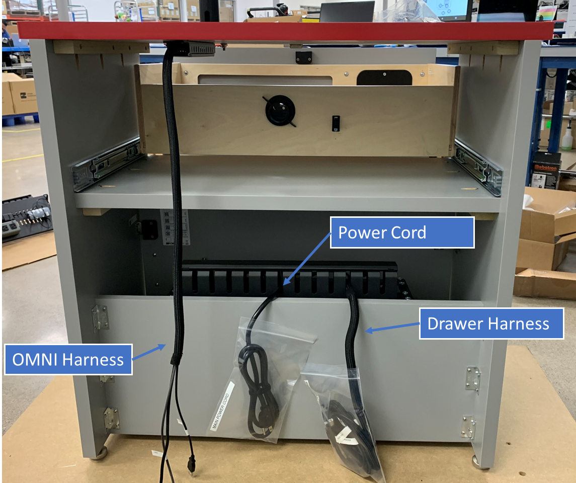
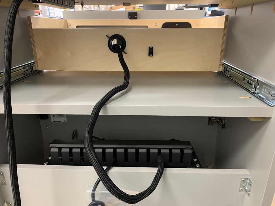
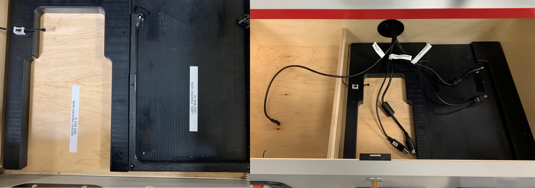
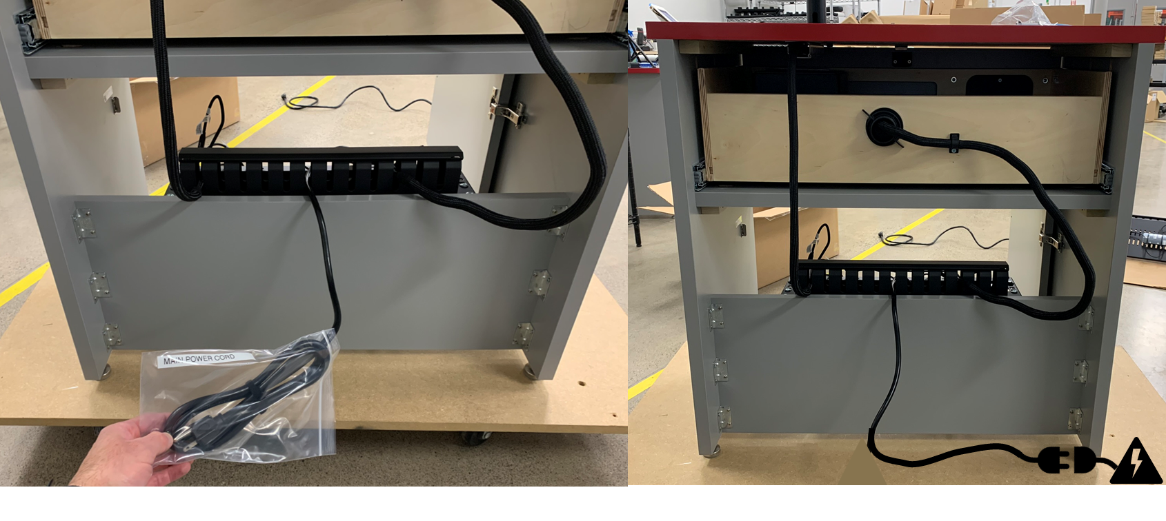
>**Note**
>At this stage, the three cable harnesses (`OMNI Harness`, `Drawer Harness`, and `Power Cord`) should be staged as shown:
>
>
---
## Step 4. Route Drawer Harness.
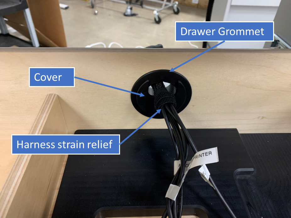
1) Remove the `cover` of the `Drawer Grommet` from within `Drawer` of the Desk.
>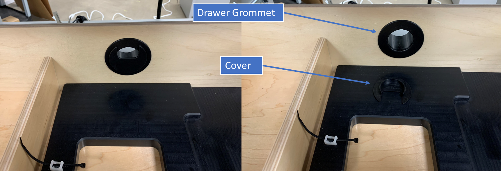
2) From the backside of the Desk route `Drawer Harness` through the `Drawer Grommet`.
>
3) Secure the `Drawer Harness` by reinstalling the `cover` of the `Drawer Grommet`. Take care to ensure the harness strain-relief (pre-installed) is located inside the drawer area and resting against the the Grommet `cover` as this will set the appropriate slack in the harness.
>
4) Latch the `harness clamp` to lock in the `Drawer Harness`.
>
>**Warning**
> Test to make sure there `Drawer Harness` has adequate slack and does not kink or bind by opening and closing `Drawer` fully.
---
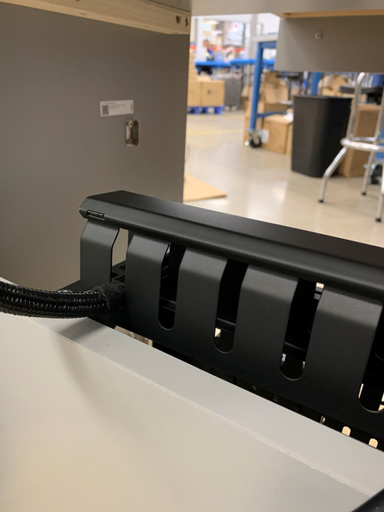
## Step 5. Connect OMNI Harness to Sub-System
1) Remove `cover` of finger duct bracket.
>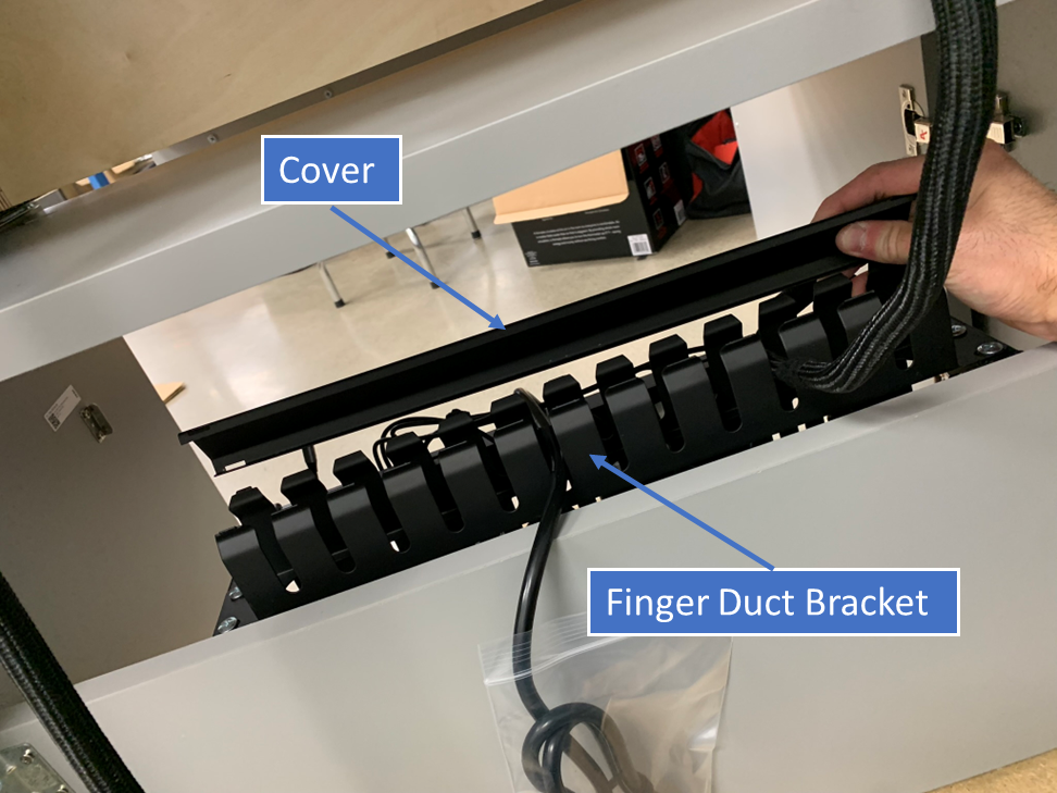
2) Route `OMNI harness` as shown in designated slot.
>
3) Reinstall finger duct `cover` to secure end of harness.
>
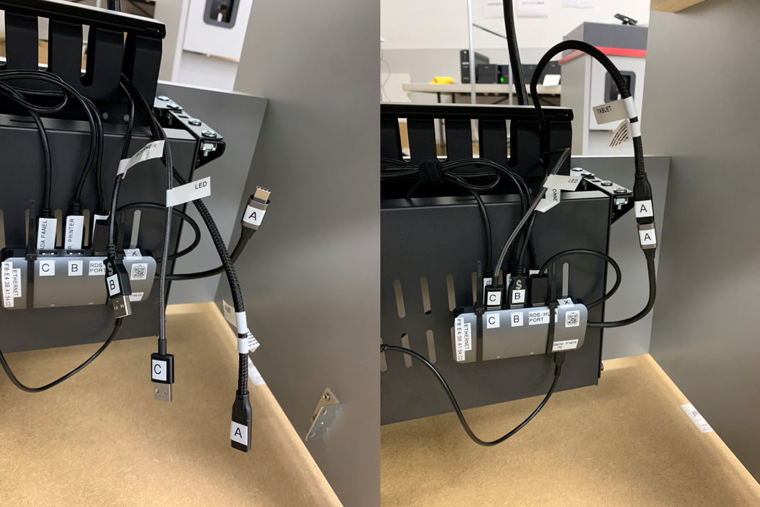
4) From inside the service comparment, connect the `OMNI Harness` to the `Sub-System` by plugging in the appropriate connections.
[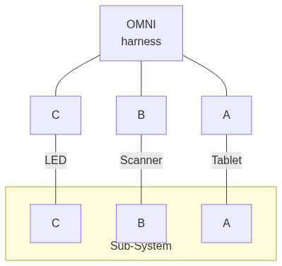](https://mermaid.live/edit#pako:eNpVkN2KwyAQhV9F5rq-QFgWmp-Whe3uRXqnuRh12oRNTDF6UUrfvdq4f4KM5zszeJgb6NkQFMDODi89O9bSSsvi2YrPw8fbi3KvPTpLy9Kx1ShF1XH-3tScc1ZFseJalB3jvNVoLbnkNYnkoZ3YJveIaiSfzH0EP1-xREr2V9X_1I49e1e0BLWGbYPi7XXxNDGRgn7fX56zVXmyyXWfK1kDG5jITTiYuIRbwhJ8TxNJKOJTjai_JEh7j40Y_NxerYbCu0AbCBeDnuoBY5wJihOOS6RkBj-7w7pWPdvTcIb7AxBhaTs)
>
---
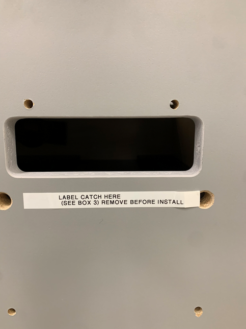
## Step 6. Install Label Catch
1) Note install location for `Label Catch` on outside face of the `Drawer`. Remove temporary label.
>
2) Using supplied hardware, install `Label Catch`.
>
---
## Step 7. Install Printers
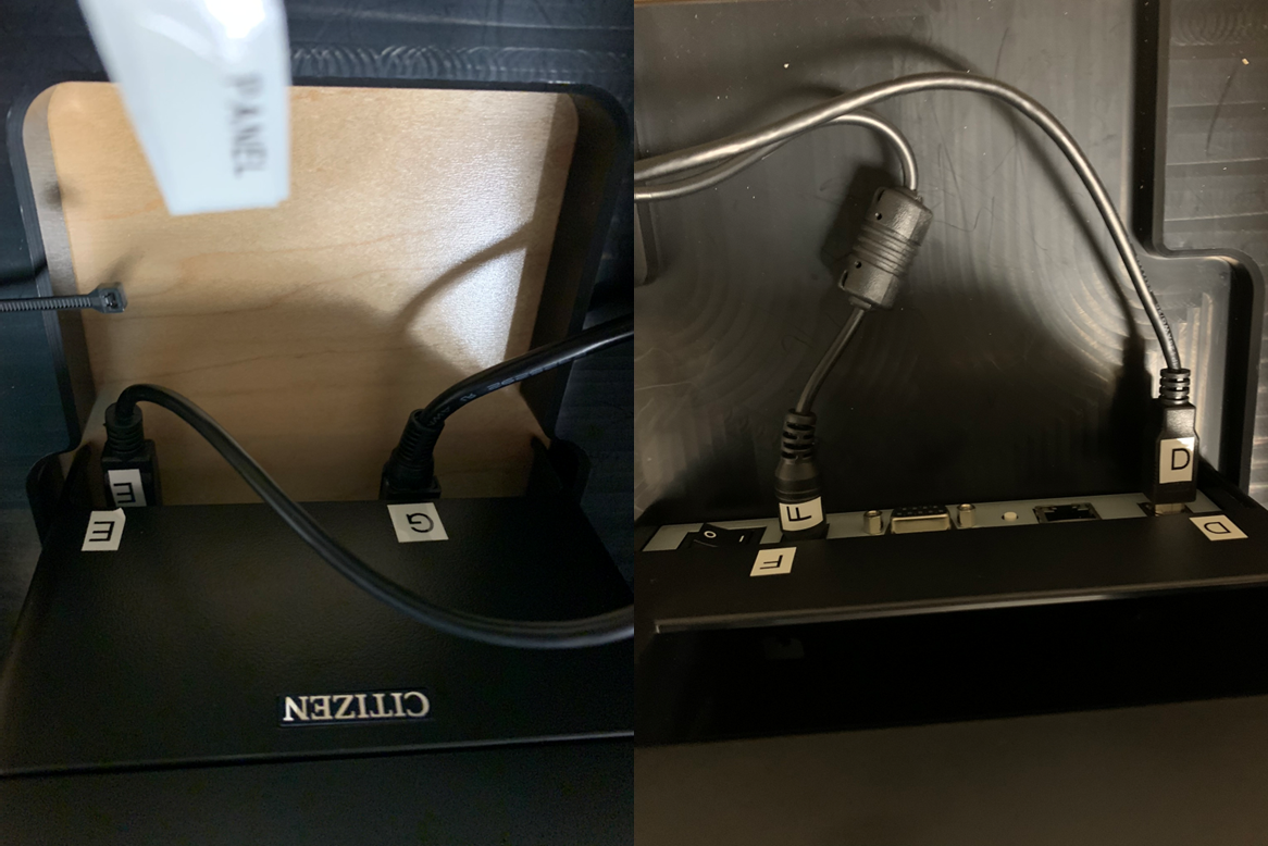
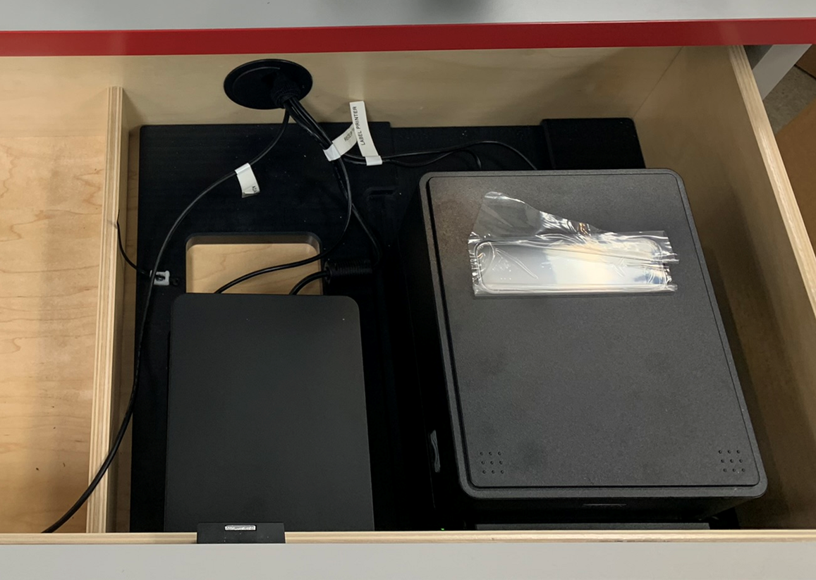
1) Note install location for `Label Printer` and `Receipt Printer` inside `Drawer` area and labeled connections.
>
2) Set `Printers` into approximate locations face down in order to access rear connections.
>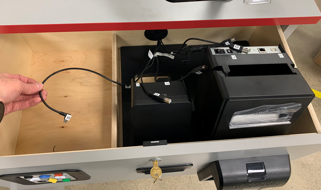
3) Connect Power and Data connection for `Label Printer` and `Receipt Printer` as labeled.
[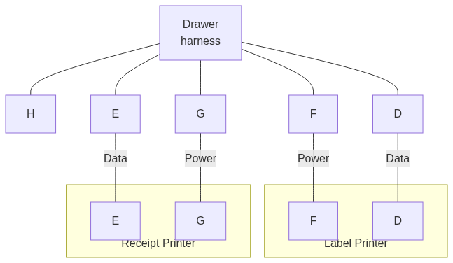](https://mermaid.live/edit#pako:eNptkd1qwzAMhV_F6Lp5gTAGa52flhXKtju7F0qiLmGJEhyHMUrffXLKQjZ2YTgc2eeTrCuUfUUQw7vDoVZv2rLlJ6MdfpJ7KNxjjY5pHM_iqiiK1Nbki96ZZNHaZItOTLro1OhzyByn4o54xoJadXINe3LKBMbP-VWSV3vLB8vEVQjYSZxGjyE0m8FanFMvfQYrn_krzguV1Az-f9KforzMLOcLK1kn7-dp0hX-MM8EG-jIddhU8n1Xy0pZ8DV1ZCEWWbRYfliwfJOLOPn-9YtLiL2baAPTUKEn3aD02kF8wXYUl6rG9-54X8i8l9s35GiIjw)
4) Re-orientate `Printers` into final installation position by "dropping" them into appropriate pockets inside the `Drawer`.
>
>**Warning**
>Take care to ensure that `Printers` are seated flat against the base of the `Drawer` for proper function.
---
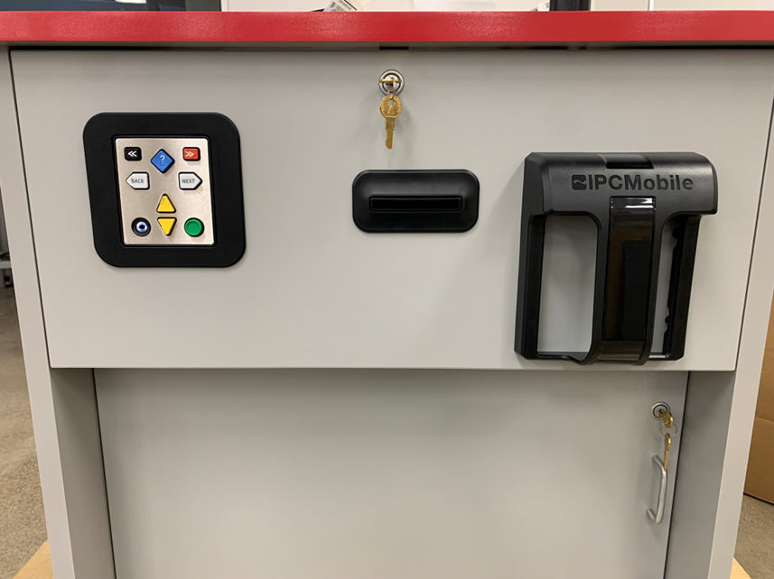
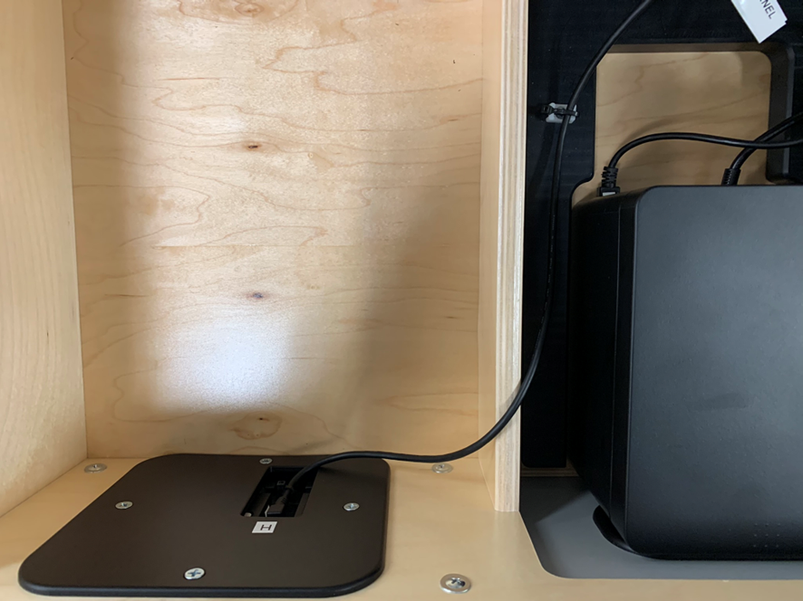
## Step 8. Connect ADA Panel
1) Note that `ADA panel` is preinstalled into `Drawer` face and the data connection port is located inside and marked.
>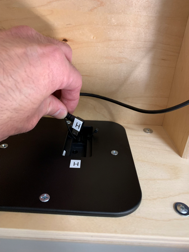
2) Route appropriate data cable as shown and connect to `ADA panel`.
[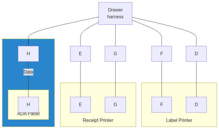](https://mermaid.live/edit#pako:eNp9kT1rwzAQhv-KUNd46VBaUwpO5I8kLYS2m5ThLF9qU1k2skwJIf-9slJE4qGD4eF09z6S70RlVyGN6ZeBviafTGihE84M_KB5Ls1LDUbjMOxdlURRRJa8CLziaWDG88ApzwJnnO2nzGEsL4pXKFGRnWm0RUP45Jh_Ny1uei30RmjU1RS08rG5VzPPhVdfKd5RYtPb_yWzJpeQC10ETeqj1_4lmefN_CXqihOWkB1od-0bWSi7yW3IJksXyMDCFLv1P_TvZLBHhUSRQ6NUfHf_9PggJV3QFk0LTeXWdHLTRFBbY4uCxg5LBfJbUKHPrhFG230ctaSxNSMu6NhXYJE14G7Z0vgAanBVrBrbmbfL4v3-z7_zJau-)

3) Tighten zipties (pre-installed) to secure cable.
>
---
## Step 9. Connect System to Power
1) Connect `Power Cord` to AC power.
>
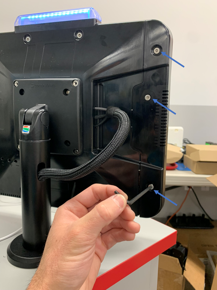
## Step 10. Install Tablet into OMNI
1) Using supplied T20 allen key, remove 3 `security screws` from OMNI `side cover`.
>**Note**
> Take note of screw lengths and their proper location. The middle screw is the longest.
2) Remove `side cover`.
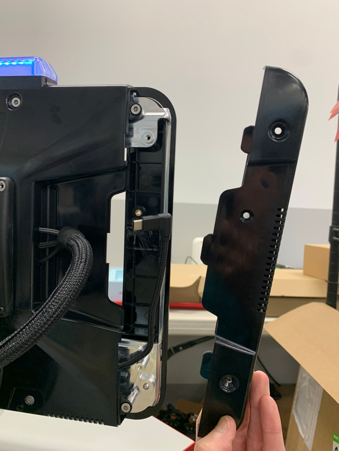
3) Slide in `Tablet`, taking care to insert with the USB-C end last.
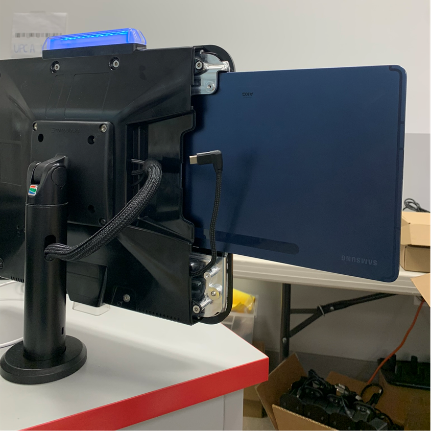
4) Seat `Tablet` fully and connect USB-C cable to `Tablet`.
5) Reinstall `side cover` and `security screws` to secure `Tablet`.
---
## Optional Step. Install Ethernet Cable (if NOT using WiFi)
1) Using supplied `Ethernet cable`, connect one end to appropriate connection on `Sub-System` located in service compartment of `RDS Desk`.
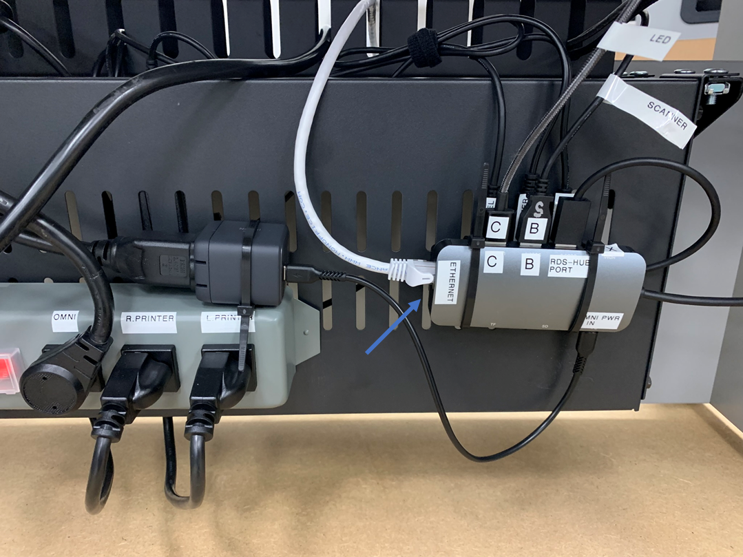
2) Connect other end to LAN network jack.
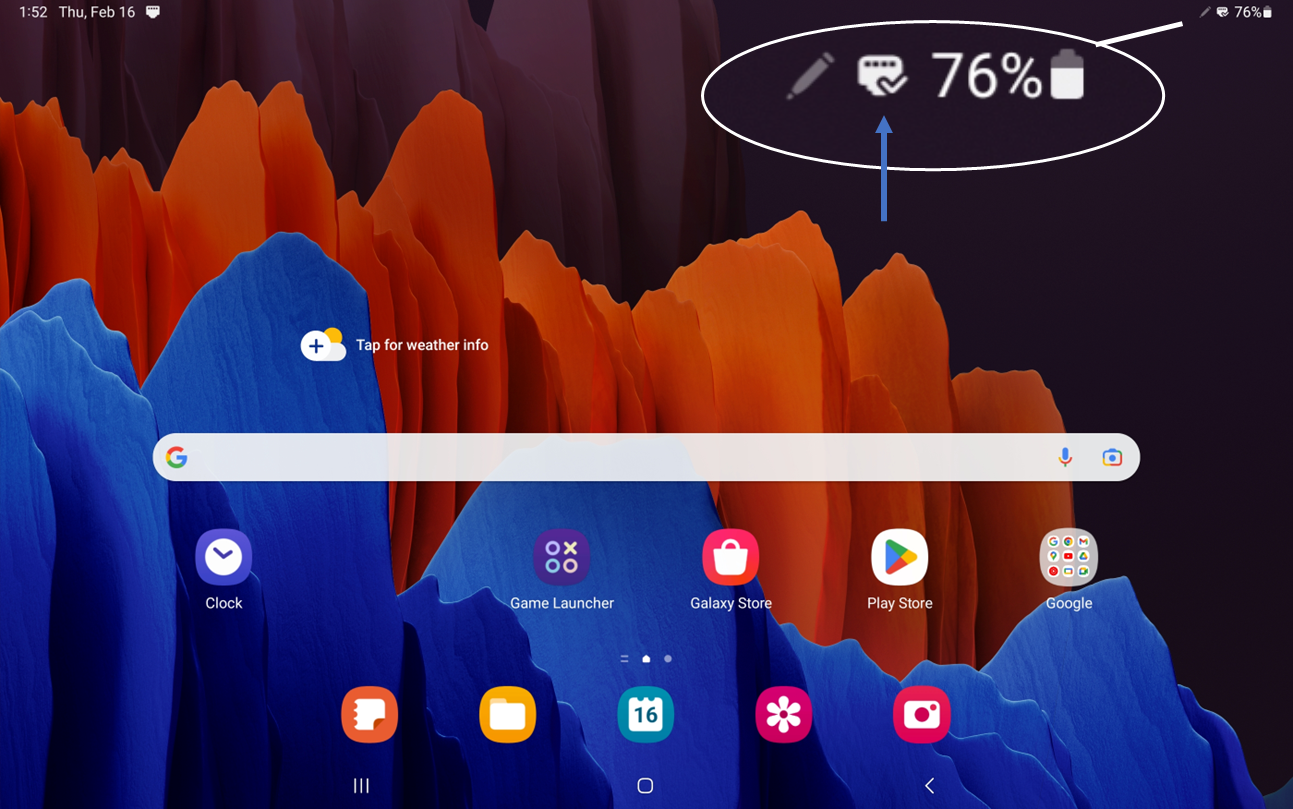
3) Network connectivity and proper connection can be confirmed on `Tablet` screen by Ethernet icon visible in upper right taskbar.
---
## System is now READY for provisioning and testing.