# NXP Cup Line Follower - Complete Documentation
## 📋 Overview
This repository contains comprehensive documentation for building and programming a line follower robot for the NXP Cup competition using the **FRDM-MCXN947** development board.
The project includes:
- **Hardware assembly guides** (shield PCB and complete car)
- **Programming tutorials** (MCUXpresso IDE setup and firmware development)
- **Component lists** with purchase links
---
## 🎯 Project Components
### Main Hardware
- **FRDM-MCXN947** - NXP Freedom development board (Arm Cortex-M33)
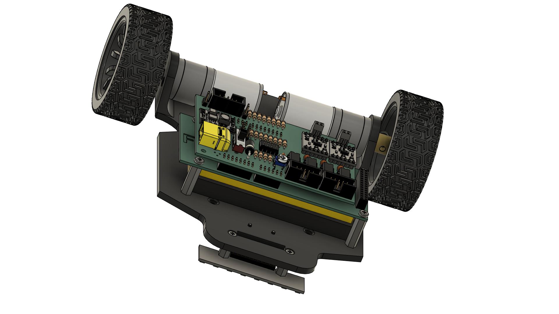
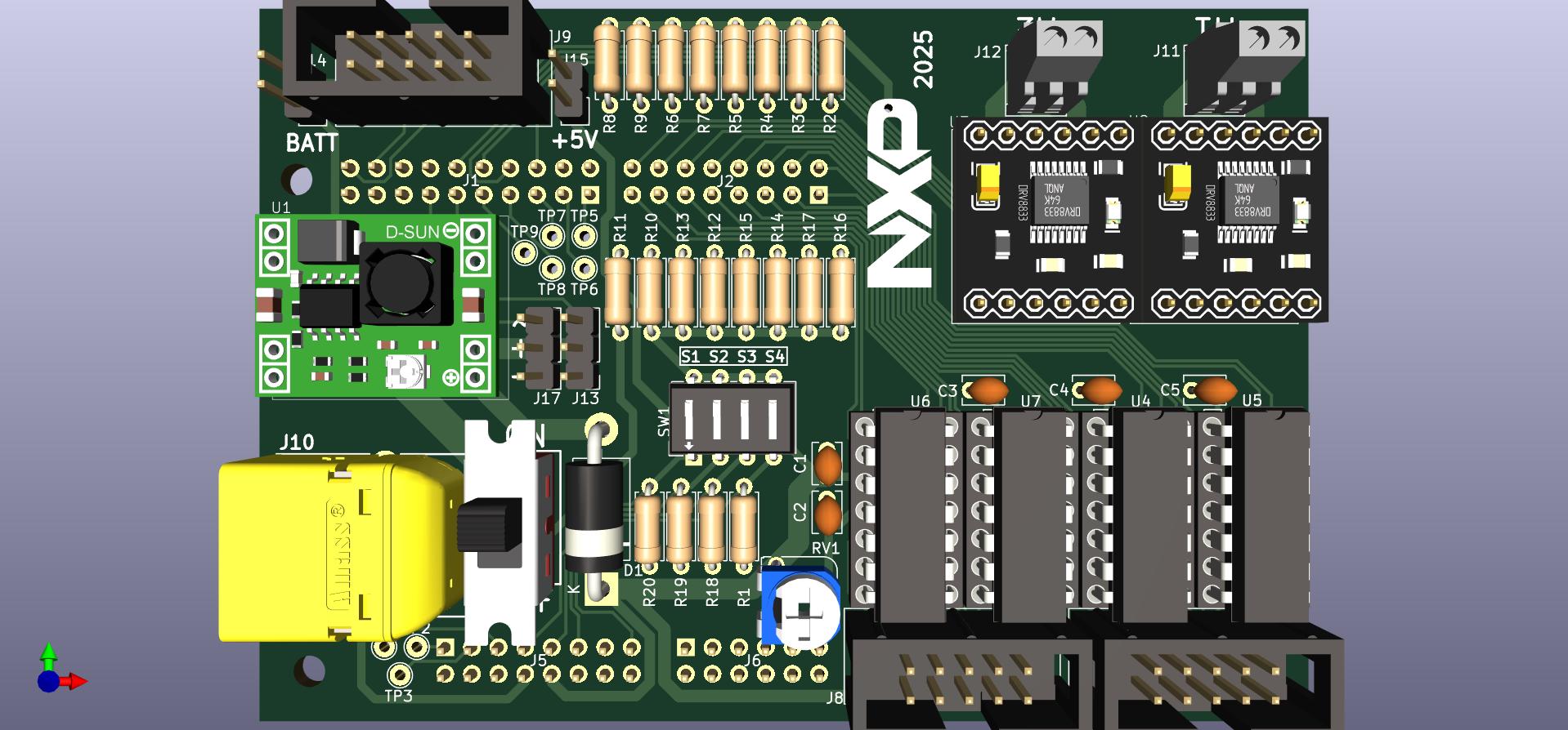
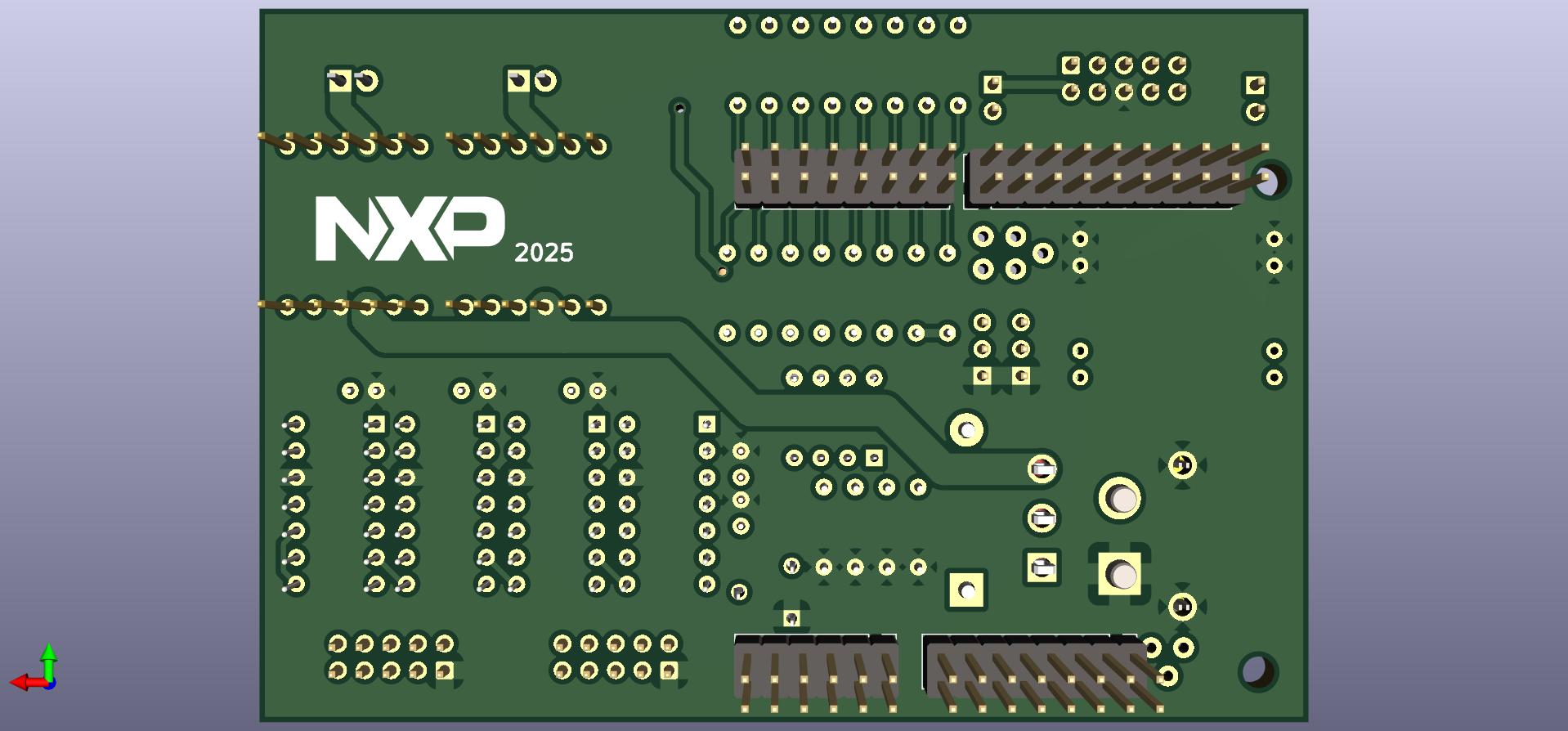
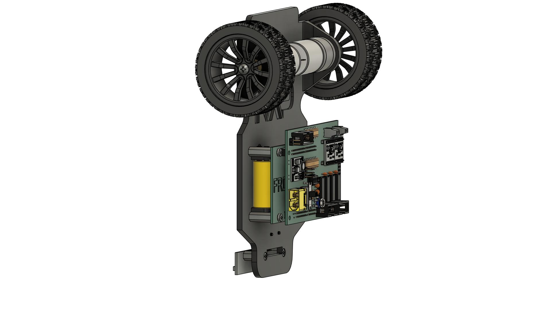
- **NXPCUP-Shield-FRDM-MCXN947** - Custom shield PCB for motor drivers and sensors
- **8x Line Sensors** - Infrared reflective sensors with LM339 comparators
- **2x DC Motors** (25GA-370) - Rear wheel drive
- **2x DRV8833** - Dual H-bridge motor drivers
- **LiPo Battery** - 7.4V 2200mAh with XT60 connector
### Software
- **MCUXpresso IDE** - Development environment
- **MCUXpresso Config Tools** - Pin and peripheral configuration
- **SDK for MCXN947** - Hardware abstraction layer
---
## 📚 Documentation Structure
### [📖 Main Tutorial](tutorial.md)
Start here for the complete assembly and programming guide.
### Detailed Guides
1. **[Component List](docs/components.md)**
- Complete bill of materials
- Purchase links
- Required tools
2. **[Shield Electronic Components](docs/shield-components.md)**
- Detailed component specifications
- Resistors, capacitors, ICs, connectors
- Polarized component warnings
3. **[Shield Assembly Guide](docs/shield-assembly.md)**
- Step-by-step soldering instructions
- 19 detailed assembly steps with images
- Quality checks and verification
- PCB cleaning
4. **[Car Assembly Guide](docs/car-assembly.md)**
- Mechanical assembly (chassis, motors, wheels)
- Electrical connections (motors, sensors, battery)
- 15 detailed steps with safety checks
- First power-on test
5. **[Programming Guide](docs/programming.md)**
- MCUXpresso IDE installation
- SDK setup
- LED blinky demo
- Project import
- Sensor reading functions
- Motor control functions
---
## 🚀 Quick Start
### 1. Gather Components
Review the [component list](docs/components.md) and order all required parts.
### 2. Assemble the Shield
Follow the [shield assembly guide](docs/shield-assembly.md) to solder all electronic components onto the PCB.
**Key steps:**
- Solder resistors, capacitors, diode
- Solder IC sockets and connectors
- Mount DC-DC converter and motor drivers
- Insert LM339 ICs
- Verify with multimeter
### 3. Assemble the Car
Follow the [car assembly guide](docs/car-assembly.md) to build the complete robot.
**Key steps:**
- Mount motors and wheels
- Install ball caster
- Mount FRDM-MCXN947 board
- Connect shield
- Mount line sensors
- Install battery
- First power-on test
### 4. Setup Programming Environment
Follow the [programming guide](docs/programming.md) to install and configure the development tools.
**Key steps:**
- Create NXP account
- Download and install MCUXpresso IDE
- Install SDK for MCXN947
- Install Config Tools
- Test with LED blinky demo
### 5. Import and Run Project
- Import the provided line follower project
- Build and download to board
- Test sensor reading and motor control
### 6. Implement Your Algorithm
Use the provided sensor and motor functions to create your own line following algorithm!
---
## 🛠️ Key Features
### Hardware
- ✅ **8 line sensors** with digital output (via LM339 comparators)
- ✅ **Differential drive** control (2 independent DC motors)
- ✅ **DRV8833 motor drivers** with PWM speed control
- ✅ **5V regulated power** from 7.4V LiPo battery (MP1584EN)
- ✅ **Modular design** with stackable shield
- ✅ **Easy debugging** via USB (MCU-LINK)
### Software
- ✅ **Pre-configured project** with sensor and motor drivers
- ✅ **Simple API** for sensor reading and motor control
- ✅ **CTIMER PWM** for smooth motor speed control
- ✅ **GPIO digital input** for fast sensor reading
- ✅ **Flexible configuration** via macros
---
## 📐 Technical Specifications
### FRDM-MCXN947
- **MCU:** MCX N947 (Arm Cortex-M33)
- **Flash:** 2MB
- **RAM:** 512KB
- **Clock:** Up to 150 MHz
- **Peripherals:** CTIMER, GPIO, UART, I2C, SPI
### Motors
- **Type:** DC geared motors (25GA-370)
- **Voltage:** 6-12V
- **Speed:** ~1000 RPM at 12V
- **Control:** PWM (0-100%) + direction (2 GPIO pins per motor)
### Sensors
- **Type:** Infrared reflective (8 sensors)
- **Output:** Digital (0/1 via LM339 comparators)
- **Detection range:** 3-5mm optimal
- **Interface:** GPIO digital input
### Power
- **Battery:** 7.4V 2S LiPo, 2200mAh
- **Regulation:** 5V @ 3A (MP1584EN step-down)
- **Connector:** XT60
---
## ⚠️ Safety Warnings
### LiPo Battery Safety
- ⚠️ **Never** short circuit battery terminals
- ⚠️ **Never** charge unattended
- ⚠️ **Always** use LiPo-specific charger
- ⚠️ **Always** store in fireproof bag
- ⚠️ Check polarity before connecting (XT60 connector)
### Soldering Safety
- ⚠️ Wear safety glasses
- ⚠️ Work in well-ventilated area
- ⚠️ Avoid touching hot soldering iron
- ⚠️ Wash hands after handling solder
### Electrical Safety
- ⚠️ Verify polarity before connecting battery
- ⚠️ Check for short circuits with multimeter
- ⚠️ Turn off power before making connections
- ⚠️ Keep liquids away from electronics
---
## 🎓 Educational Objectives
This project teaches:
- **Electronics:** PCB assembly, soldering, component identification
- **Embedded systems:** Microcontroller programming, peripheral configuration
- **Control systems:** PWM, GPIO, sensor interfacing
- **Robotics:** Differential drive, line following algorithms
- **Debugging:** Multimeter usage, troubleshooting hardware/software
---
## 🤝 Contributing
This is an educational project for the NXP Cup competition. Contributions are welcome!
**How to contribute:**
1. Fork the repository
2. Create a feature branch (`git checkout -b feature/improvement`)
3. Commit your changes (`git commit -m 'Add improvement'`)
4. Push to the branch (`git push origin feature/improvement`)
5. Open a Pull Request
**Areas for contribution:**
- Additional assembly photos
- Code examples
- Algorithm improvements
- Translations
---
## 📄 License
This project is open source and available under the following licenses:
- **Hardware (PCB, schematics):** CERN Open Hardware Licence v2 - Strongly Reciprocal (CERN-OHL-S-2.0)
- **Documentation (markdown, images):** Creative Commons Attribution-ShareAlike 4.0 (CC BY-SA 4.0)
- **Software (firmware, code examples):** MIT License
See [LICENSE](LICENSE) for details.
---
## 🔗 Resources
### Official Documentation
- [FRDM-MCXN947 Product Page](https://www.nxp.com/design/design-center/development-boards-and-designs/FRDM-MCXN947)
- [MCUXpresso IDE](https://www.nxp.com/mcuxpresso/ide)
- [MCUXpresso Config Tools](https://www.nxp.com/design/design-center/software/development-software/mcuxpresso-software-and-tools-/mcuxpresso-config-tools-pins-clocks-and-peripherals:MCUXpresso-Config-Tools)
### Datasheets
- [DRV8833 Motor Driver](https://www.ti.com/product/DRV8833)
- [LM339 Comparator](https://www.ti.com/product/LM339)
### Community
- [NXP Cup Official Website](https://www.nxp.com/nxpcup)
- [NXP Community Forums](https://community.nxp.com/)
---
## 📧 Support
For questions or issues:
- Search existing [GitHub Issues](https://github.com/cristiannxp/NXP_Linefollower/issues)
- Open a new issue with detailed description
---
## 🏆 Acknowledgments
- **NXP Semiconductors** - for the FRDM-MCXN947 platform and NXP Cup competition
- **Contributors** - everyone who helped improve this documentation
- **Students** - who will build amazing line followers with this guide!
---
## 📸 Gallery
---
**Ready to build your line follower? Start with the [Main Tutorial](tutorial.md)!** 🚗💨
---
Made with ❤️ for NXP Cup