# NXP Cup Car - Complete Assembly Guide
[← Back to Main](../tutorial.md) | [← Shield Assembly](shield-assembly.md)
## Assembly Steps Overview
1. [Chassis Preparation](#step-1-chassis-preparation)
2. [Mounting Motors](#step-2-mounting-motors-on-chassis)
3. [Installing HEX Adapters](#step-3-installing-hex-adapters)
4. [Mounting Wheels](#step-4-mounting-wheels)
5. [Installing Ball Caster](#step-5-installing-ball-caster)
6. [Mounting Spacers](#step-6-mounting-spacers-for-frdm-mcxn947)
7. [Mounting FRDM Board](#step-7-mounting-frdm-mcxn947-board)
8. [Connecting Shield](#step-8-connecting-nxpcup-shield)
9. [Connecting Motors](#step-9-connecting-motors-to-shield)
10. [Mounting Line Sensors](#step-10-mounting-line-sensors)
11. [Connecting Ribbon Cable](#step-11-connecting-ribbon-cable)
12. [Installing Battery](#step-12-installing-battery)
13. [Connecting Battery](#step-13-connecting-battery-to-shield)
14. [Final Checks](#step-14-final-checks-before-power-on)
15. [First Power-On Test](#step-15-first-power-on-test)
---
## Before You Begin
### Required Components
- [ ] Assembled NXPCUP-Shield (from [Shield Assembly Guide](shield-assembly.md))
- [ ] FRDM-MCXN947 development board
- [ ] 3D printed chassis or base plate
- [ ] 2x DC motors (25GA-370)
- [ ] 2x Wheels (65mm)
- [ ] 2x HEX adapters
- [ ] 1x Ball caster
- [ ] Line sensor array
- [ ] Ribbon cable
- [ ] 16x M3 screws (6mm length)
- [ ] 2x M3 x 10mm spacers
- [ ] 4x M3 x 20mm spacers
- [ ] LiPo battery 7.4V 2200mAh with XT60 connector
### Required Tools
- [ ] Phillips screwdriver (for M3 screws)
- [ ] Pliers
- [ ] Multimeter
- [ ] Cable ties/zip ties
### Safety Precautions
- ⚠️ **Battery Safety:**
- Never connect battery with reversed polarity
- Never short circuit battery terminals
- Keep battery away from metal objects
- Charge only with appropriate LiPo charger
- Never leave charging battery unattended
- **Mechanical Safety:**
- Ensure all screws are tight before operation
- Keep fingers away from moving parts
- Wear safety glasses when cutting or drilling
---
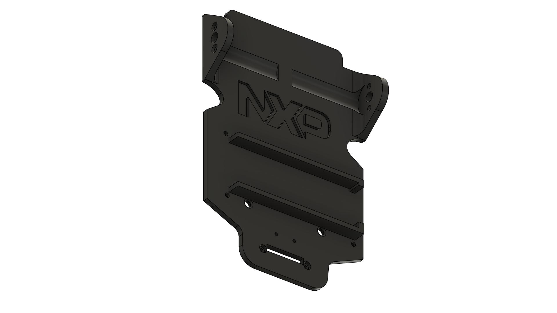
## Step 1: Chassis Preparation
 ### Instructions
1. **Inspect the chassis:**
- Check for any defects or rough edges
- If 3D printed, remove any support material
- Sand rough edges if necessary
2. **Identify mounting points:**
- Motor mounting holes (usually 4 holes per motor)
- Ball caster mounting holes (usually 2 holes)
- Board mounting holes (usually 4 holes)
- Sensor mounting holes (usually 2-4 holes)
3. **Clean the chassis:**
- Remove any dust or debris
- Ensure mounting surfaces are flat
4. **Organize hardware:**
- Separate screws by type
- Have spacers ready
- Keep small parts in containers
### Quality Check
- [ ] Chassis is clean and free of defects
- [ ] All mounting holes are clear and accessible
- [ ] Mounting surfaces are flat
- [ ] All hardware is organized and ready
---
## Step 2: Mounting Motors on Chassis
### Instructions
1. **Inspect the chassis:**
- Check for any defects or rough edges
- If 3D printed, remove any support material
- Sand rough edges if necessary
2. **Identify mounting points:**
- Motor mounting holes (usually 4 holes per motor)
- Ball caster mounting holes (usually 2 holes)
- Board mounting holes (usually 4 holes)
- Sensor mounting holes (usually 2-4 holes)
3. **Clean the chassis:**
- Remove any dust or debris
- Ensure mounting surfaces are flat
4. **Organize hardware:**
- Separate screws by type
- Have spacers ready
- Keep small parts in containers
### Quality Check
- [ ] Chassis is clean and free of defects
- [ ] All mounting holes are clear and accessible
- [ ] Mounting surfaces are flat
- [ ] All hardware is organized and ready
---
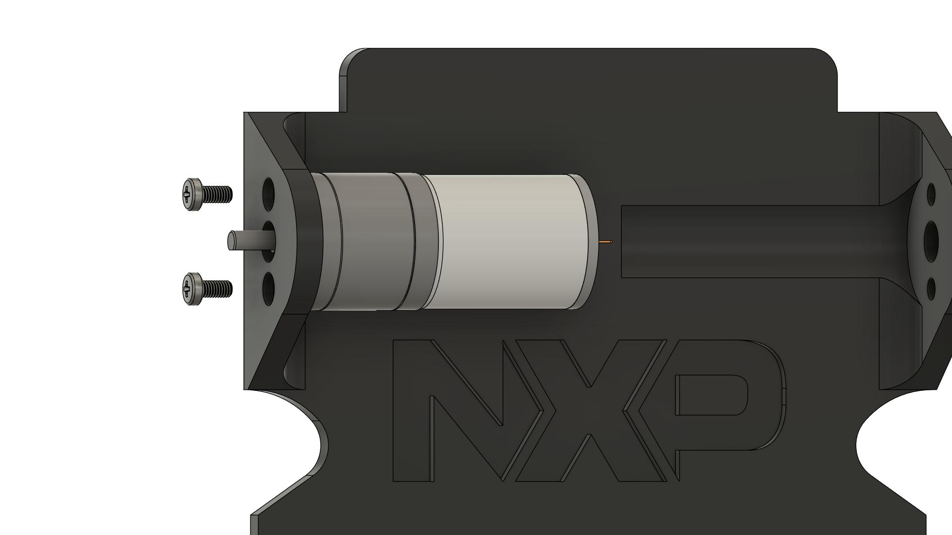
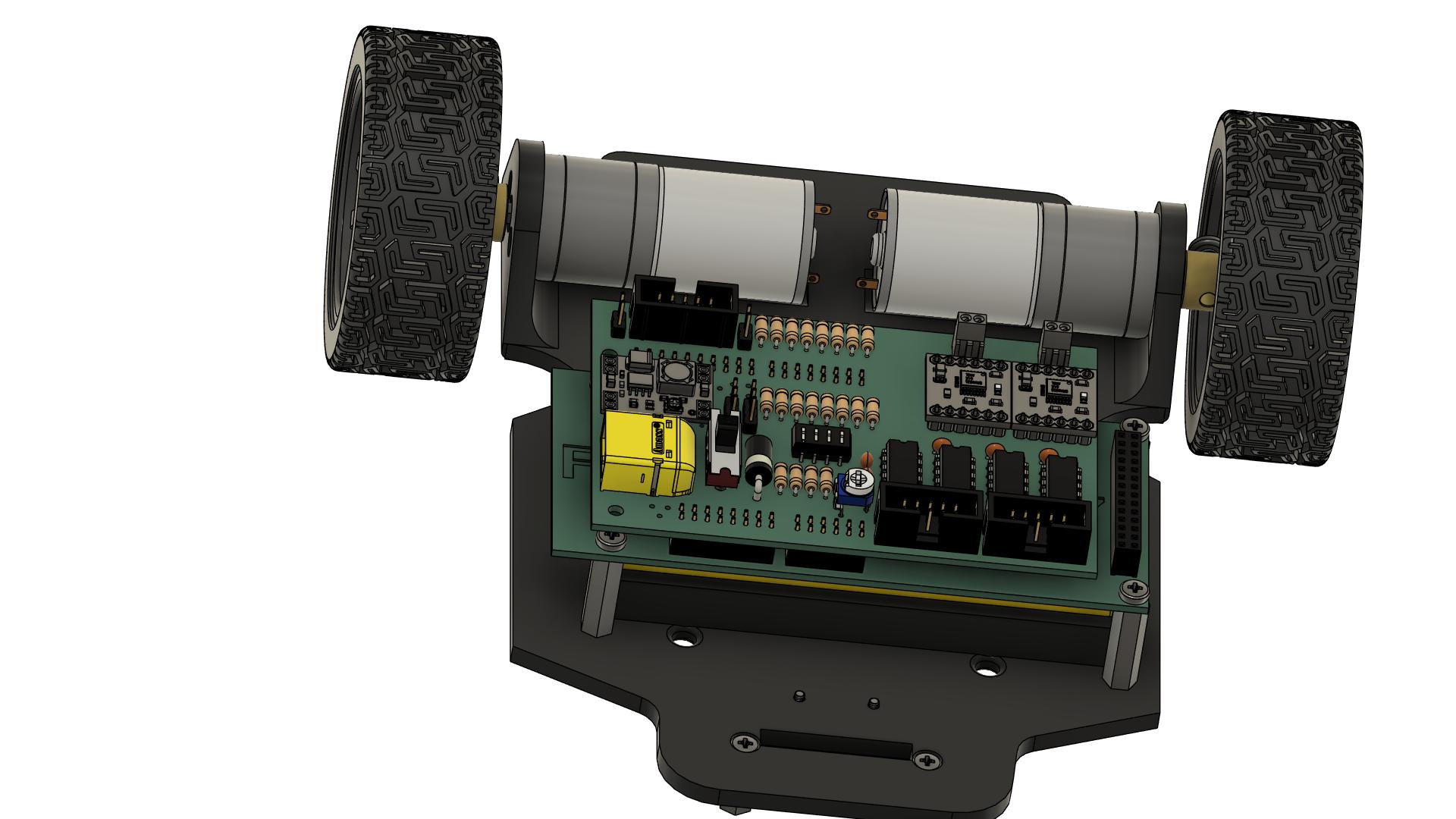
## Step 2: Mounting Motors on Chassis
 ### Instructions
1. **Identify motor positions:**
- Left motor position
- Right motor position
- Motors should be parallel to each other
2. **Position the first motor (left):**
- Align motor mounting holes with chassis holes
- Motor shaft should point outward (toward wheel position)
- Motor body should be inside the chassis
3. **Insert screws:**
- Use 2x M3 x 6mm screws per motor
- Insert screws from the external side of chassis
- Do not fully tighten yet
4. **Align the motor:**
- Ensure motor is perpendicular to chassis
- Motor shaft should be parallel to ground
- Adjust position if needed
5. **Tighten screws:**
- Tighten in a cross pattern (opposite corners)
- Tighten evenly to avoid misalignment
- Ensure motor is firmly mounted
6. **Repeat for second motor (right):**
- Same procedure as left motor
- Ensure both motors are aligned parallel
7. **Verify motor alignment:**
- Both motor shafts should be at same height
- Both shafts should be parallel
- Rotate shafts by hand - should turn freely
### Quality Check
- [ ] Both motors are securely mounted (8 screws total)
- [ ] Motors are parallel to each other
- [ ] Motor shafts are at same height
- [ ] Motor shafts rotate freely without binding
- [ ] All screws are tight
- [ ] Motors do not wobble
**Note:** Proper motor alignment is critical for straight driving!
---
## Step 3: Installing HEX Adapters
### Instructions
1. **Identify motor positions:**
- Left motor position
- Right motor position
- Motors should be parallel to each other
2. **Position the first motor (left):**
- Align motor mounting holes with chassis holes
- Motor shaft should point outward (toward wheel position)
- Motor body should be inside the chassis
3. **Insert screws:**
- Use 2x M3 x 6mm screws per motor
- Insert screws from the external side of chassis
- Do not fully tighten yet
4. **Align the motor:**
- Ensure motor is perpendicular to chassis
- Motor shaft should be parallel to ground
- Adjust position if needed
5. **Tighten screws:**
- Tighten in a cross pattern (opposite corners)
- Tighten evenly to avoid misalignment
- Ensure motor is firmly mounted
6. **Repeat for second motor (right):**
- Same procedure as left motor
- Ensure both motors are aligned parallel
7. **Verify motor alignment:**
- Both motor shafts should be at same height
- Both shafts should be parallel
- Rotate shafts by hand - should turn freely
### Quality Check
- [ ] Both motors are securely mounted (8 screws total)
- [ ] Motors are parallel to each other
- [ ] Motor shafts are at same height
- [ ] Motor shafts rotate freely without binding
- [ ] All screws are tight
- [ ] Motors do not wobble
**Note:** Proper motor alignment is critical for straight driving!
---
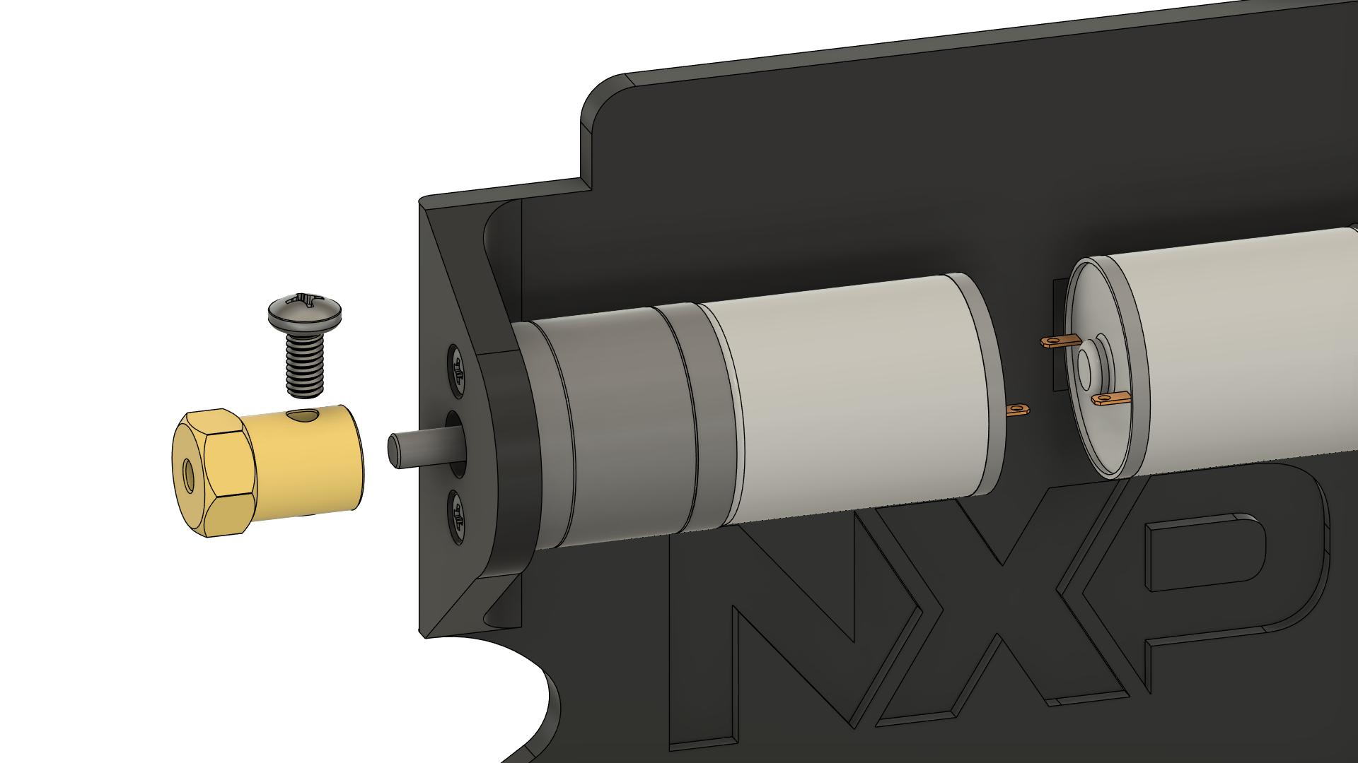
## Step 3: Installing HEX Adapters
 ### Instructions
1. **Prepare HEX adapters:**
- Take the 2 HEX adapters
- Identify the set screw on each adapter
- Loosen the set screw (do not remove completely)
2. **Check motor shaft:**
- Most motors have a flat side on the shaft (D-shaft)
- This flat side prevents the adapter from slipping
- Clean the shaft if needed
3. **Install first adapter (left motor):**
- Slide the HEX adapter onto the motor shaft
- Push it on as far as it will go
- Align the set screw with the flat side of the shaft
4. **Tighten the set screw:**
- Tighten firmly but do not over-tighten
- The adapter should not slip on the shaft
5. **Test the connection:**
- Try to rotate the adapter by hand
- It should not slip on the motor shaft
- The motor shaft should rotate with the adapter
6. **Repeat for second adapter (right motor):**
- Same procedure
7. **Verify both adapters:**
- Both should be pushed fully onto shafts
- Both should be tight and not slip
- Both should be at same distance from motor body
### Quality Check
- [ ] Both HEX adapters are installed
- [ ] Adapters are pushed fully onto motor shafts
- [ ] Set screws are aligned with flat side of shaft
- [ ] Set screws are tight
- [ ] Adapters do not slip when rotated by hand
- [ ] Both adapters are at same position on shafts
**⚠️ IMPORTANT:** If adapters slip during operation, the wheels will not turn properly!
---
## Step 4: Mounting Wheels
### Instructions
1. **Prepare HEX adapters:**
- Take the 2 HEX adapters
- Identify the set screw on each adapter
- Loosen the set screw (do not remove completely)
2. **Check motor shaft:**
- Most motors have a flat side on the shaft (D-shaft)
- This flat side prevents the adapter from slipping
- Clean the shaft if needed
3. **Install first adapter (left motor):**
- Slide the HEX adapter onto the motor shaft
- Push it on as far as it will go
- Align the set screw with the flat side of the shaft
4. **Tighten the set screw:**
- Tighten firmly but do not over-tighten
- The adapter should not slip on the shaft
5. **Test the connection:**
- Try to rotate the adapter by hand
- It should not slip on the motor shaft
- The motor shaft should rotate with the adapter
6. **Repeat for second adapter (right motor):**
- Same procedure
7. **Verify both adapters:**
- Both should be pushed fully onto shafts
- Both should be tight and not slip
- Both should be at same distance from motor body
### Quality Check
- [ ] Both HEX adapters are installed
- [ ] Adapters are pushed fully onto motor shafts
- [ ] Set screws are aligned with flat side of shaft
- [ ] Set screws are tight
- [ ] Adapters do not slip when rotated by hand
- [ ] Both adapters are at same position on shafts
**⚠️ IMPORTANT:** If adapters slip during operation, the wheels will not turn properly!
---
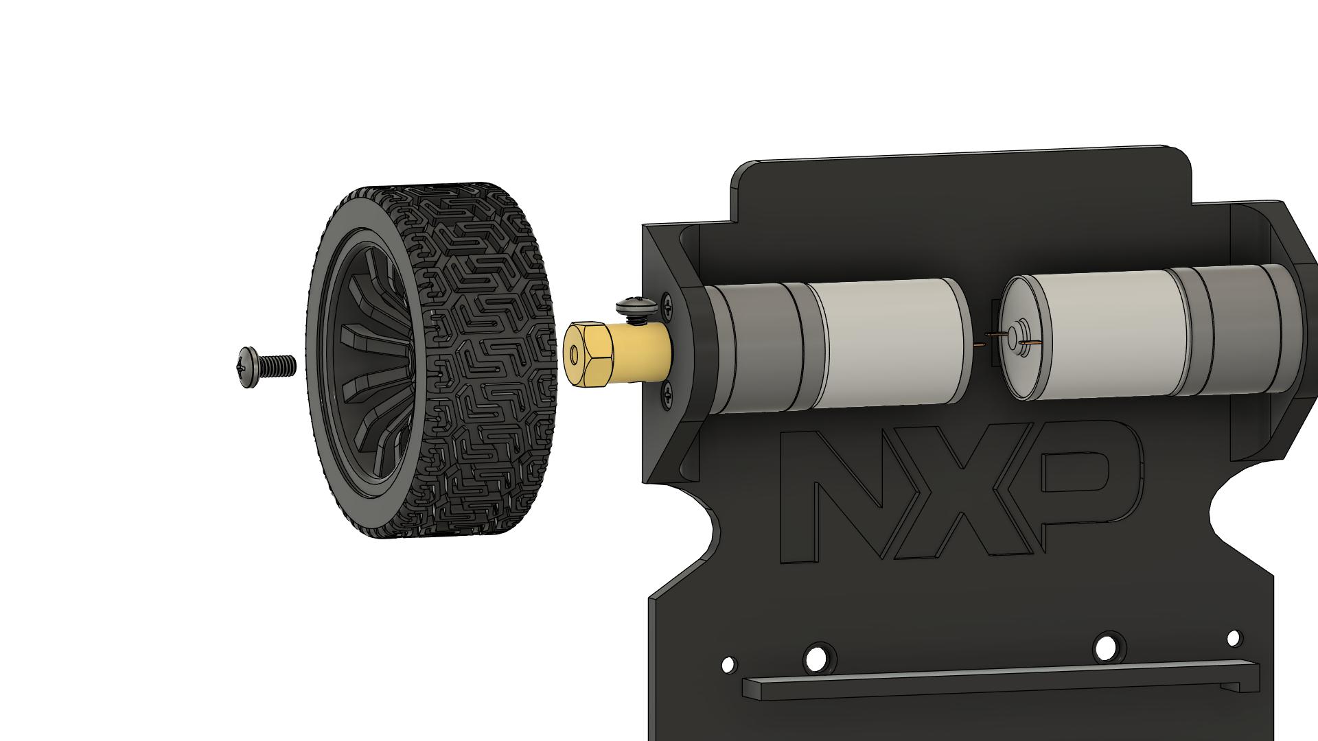
## Step 4: Mounting Wheels
 ### Instructions
1. **Prepare wheels:**
- Take the 2 wheels (65mm diameter)
- Check that the hexagonal hole is clean
- Remove any manufacturing debris
2. **Install first wheel (left):**
- Align the hexagonal hole in the wheel with the HEX adapter
- Push the wheel onto the adapter
- The wheel should slide on smoothly
- Push until the wheel is fully seated
3. **Secure the wheel:**
- Most wheels have a set screw or retaining screw
- Insert and tighten the screw
- Ensure the wheel is firmly attached
4. **Test the wheel:**
- Rotate the wheel by hand
- It should turn the motor shaft
- No wobbling or play
5. **Repeat for second wheel (right):**
- Same procedure
6. **Check wheel alignment:**
- Both wheels should be parallel
- Both wheels should be at same height
- Spin each wheel - should rotate freely
- No rubbing against chassis
### Quality Check
- [ ] Both wheels are installed
- [ ] Wheels are fully seated on HEX adapters
- [ ] Retaining screws are tight
- [ ] Wheels are parallel to each other
- [ ] Wheels rotate freely without wobbling
- [ ] Wheels do not rub against chassis
- [ ] Both wheels are at same height from ground
**Note:** Wheel alignment affects driving performance. Ensure they are parallel!
---
## Step 5: Installing Ball Caster
### Instructions
1. **Prepare wheels:**
- Take the 2 wheels (65mm diameter)
- Check that the hexagonal hole is clean
- Remove any manufacturing debris
2. **Install first wheel (left):**
- Align the hexagonal hole in the wheel with the HEX adapter
- Push the wheel onto the adapter
- The wheel should slide on smoothly
- Push until the wheel is fully seated
3. **Secure the wheel:**
- Most wheels have a set screw or retaining screw
- Insert and tighten the screw
- Ensure the wheel is firmly attached
4. **Test the wheel:**
- Rotate the wheel by hand
- It should turn the motor shaft
- No wobbling or play
5. **Repeat for second wheel (right):**
- Same procedure
6. **Check wheel alignment:**
- Both wheels should be parallel
- Both wheels should be at same height
- Spin each wheel - should rotate freely
- No rubbing against chassis
### Quality Check
- [ ] Both wheels are installed
- [ ] Wheels are fully seated on HEX adapters
- [ ] Retaining screws are tight
- [ ] Wheels are parallel to each other
- [ ] Wheels rotate freely without wobbling
- [ ] Wheels do not rub against chassis
- [ ] Both wheels are at same height from ground
**Note:** Wheel alignment affects driving performance. Ensure they are parallel!
---
## Step 5: Installing Ball Caster
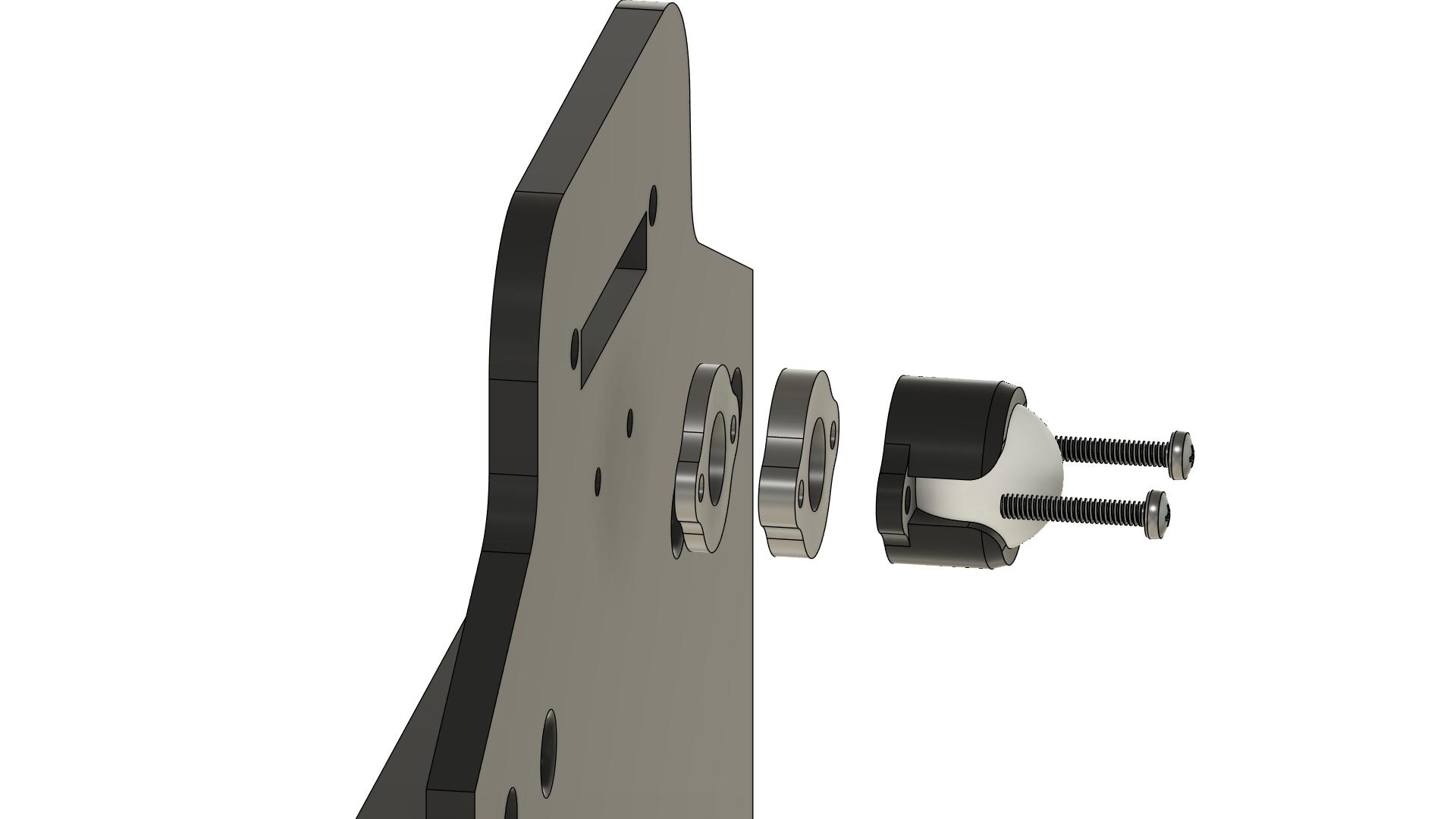 ### Instructions
1. **Identify ball caster position:**
- Mounted at front of chassis
- Should be centered left-to-right
- Position determines weight distribution
2. **Position the ball caster:**
- Place ball caster on mounting surface
- Align mounting holes with chassis holes
- Ball should face downward
3. **Check height:**
- With wheels on ground, chassis should be level
- Ball caster should just touch the ground
- Adjust if chassis has multiple mounting positions
4. **Insert screws:**
- Use 2 x M3 x 6mm screws
- Insert from bottom of chassis
5. **Tighten screws:**
- Tighten evenly
- Ensure ball caster is firmly mounted
6. **Test the ball caster:**
- Ball should rotate freely in all directions
- No binding or sticking
- Should roll smoothly
### Quality Check
- [ ] Ball caster is mounted securely (2 screws)
- [ ] Ball caster is centered on chassis
- [ ] Ball rotates freely in all directions
- [ ] Chassis is level when on wheels and ball caster
- [ ] All screws are tight
**Note:** The ball caster provides the third point of support. Proper height is important for stability.
---
## Step 6: Mounting Spacers for FRDM-MCXN947
### Instructions
1. **Identify ball caster position:**
- Mounted at front of chassis
- Should be centered left-to-right
- Position determines weight distribution
2. **Position the ball caster:**
- Place ball caster on mounting surface
- Align mounting holes with chassis holes
- Ball should face downward
3. **Check height:**
- With wheels on ground, chassis should be level
- Ball caster should just touch the ground
- Adjust if chassis has multiple mounting positions
4. **Insert screws:**
- Use 2 x M3 x 6mm screws
- Insert from bottom of chassis
5. **Tighten screws:**
- Tighten evenly
- Ensure ball caster is firmly mounted
6. **Test the ball caster:**
- Ball should rotate freely in all directions
- No binding or sticking
- Should roll smoothly
### Quality Check
- [ ] Ball caster is mounted securely (2 screws)
- [ ] Ball caster is centered on chassis
- [ ] Ball rotates freely in all directions
- [ ] Chassis is level when on wheels and ball caster
- [ ] All screws are tight
**Note:** The ball caster provides the third point of support. Proper height is important for stability.
---
## Step 6: Mounting Spacers for FRDM-MCXN947
 ### Instructions
1. **Identify board mounting positions:**
- Chassis have 4 mounting holes for the development board
- These holes match the FRDM-MCXN947 mounting holes
2. **Determine spacer configuration:**
- **All positions:** 4 x M3 x 20mm spacers
- This provides proper height for the FRDM board mounting
3. **Install spacers (20mm):**
- Take 4x M3 x 20mm spacers
- Position at all 4 mounting holes
- Insert M3 x 6mm screw from bottom of chassis
- Screw into the spacer from below
- Tighten securely
5. **Verify spacer installation:**
- All 4 spacers should be perpendicular to chassis
- Spacers should be firmly attached
- No wobbling
### Quality Check
- [ ] 2x M3 x 20mm spacers installed at rear positions
- [ ] 2x M3 x 10mm spacers installed at front positions
- [ ] All spacers are perpendicular to chassis
- [ ] All spacers are tight (4 screws from bottom)
- [ ] Spacers do not wobble
**Note:** The different spacer heights create a slight tilt, which can help with sensor positioning.
---
## Step 7: Mounting Spacers for Line Sensors
### Instructions
1. **Identify board mounting positions:**
- Chassis have 4 mounting holes for the development board
- These holes match the FRDM-MCXN947 mounting holes
2. **Determine spacer configuration:**
- **All positions:** 4 x M3 x 20mm spacers
- This provides proper height for the FRDM board mounting
3. **Install spacers (20mm):**
- Take 4x M3 x 20mm spacers
- Position at all 4 mounting holes
- Insert M3 x 6mm screw from bottom of chassis
- Screw into the spacer from below
- Tighten securely
5. **Verify spacer installation:**
- All 4 spacers should be perpendicular to chassis
- Spacers should be firmly attached
- No wobbling
### Quality Check
- [ ] 2x M3 x 20mm spacers installed at rear positions
- [ ] 2x M3 x 10mm spacers installed at front positions
- [ ] All spacers are perpendicular to chassis
- [ ] All spacers are tight (4 screws from bottom)
- [ ] Spacers do not wobble
**Note:** The different spacer heights create a slight tilt, which can help with sensor positioning.
---
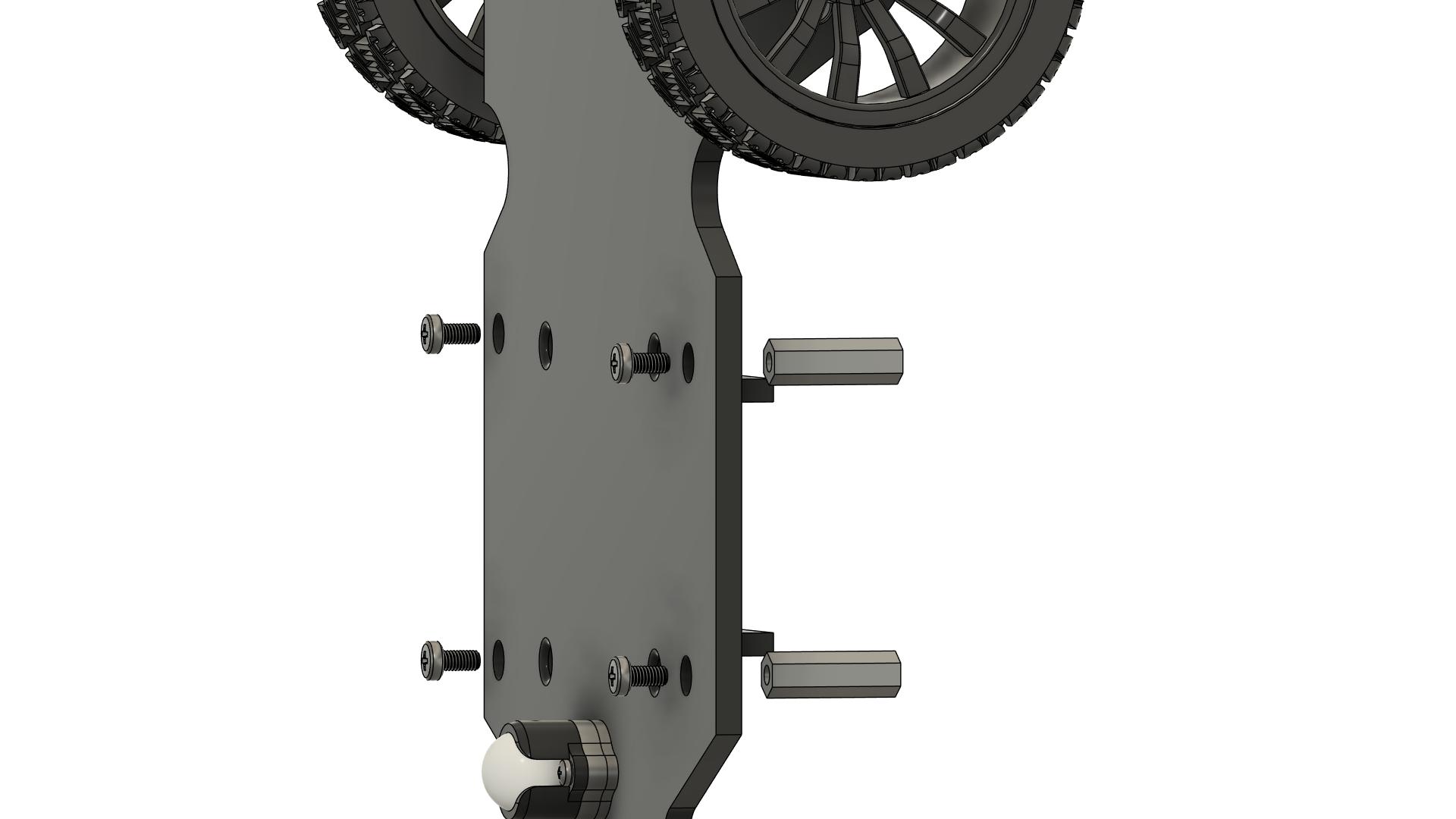
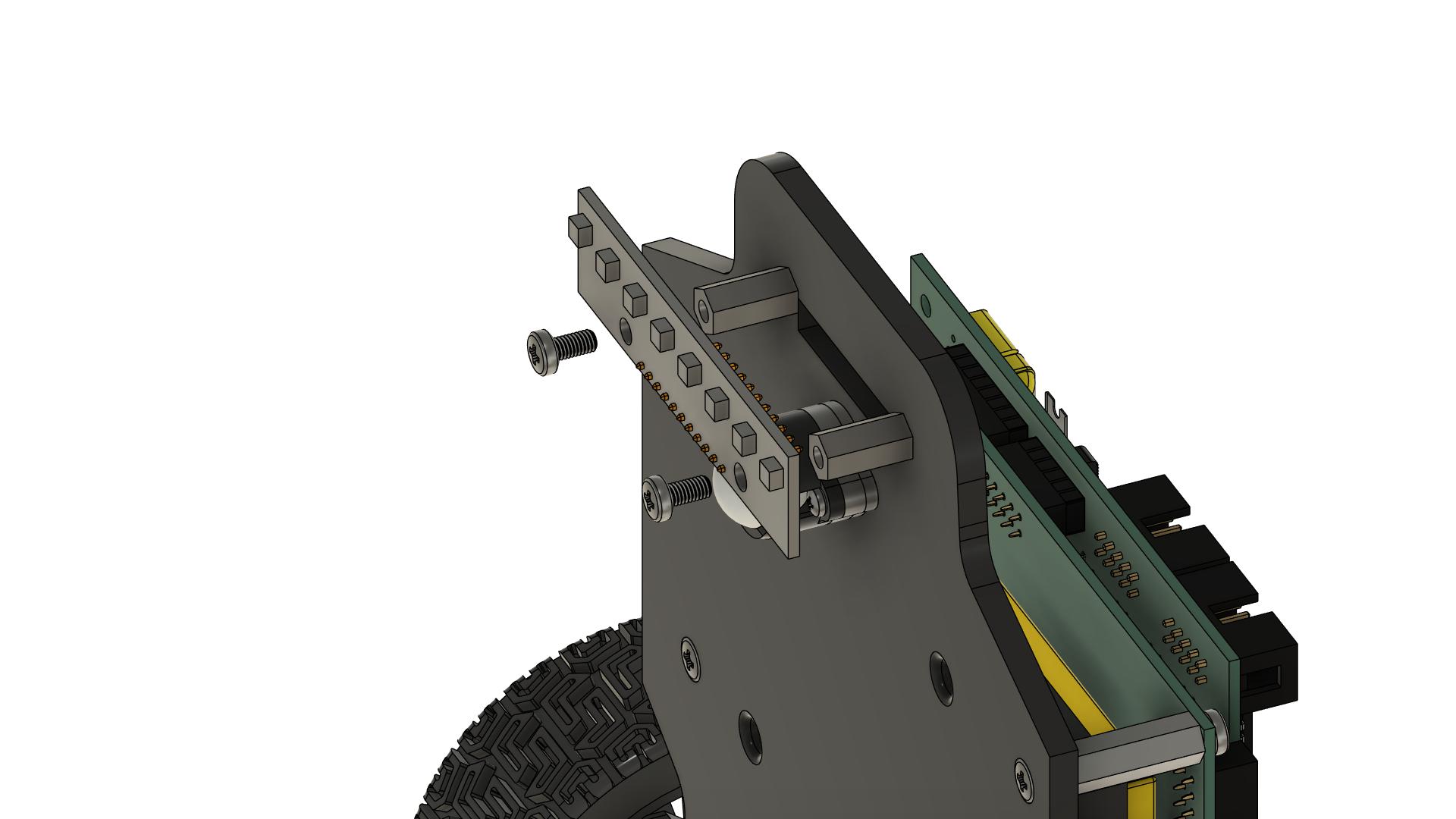
## Step 7: Mounting Spacers for Line Sensors
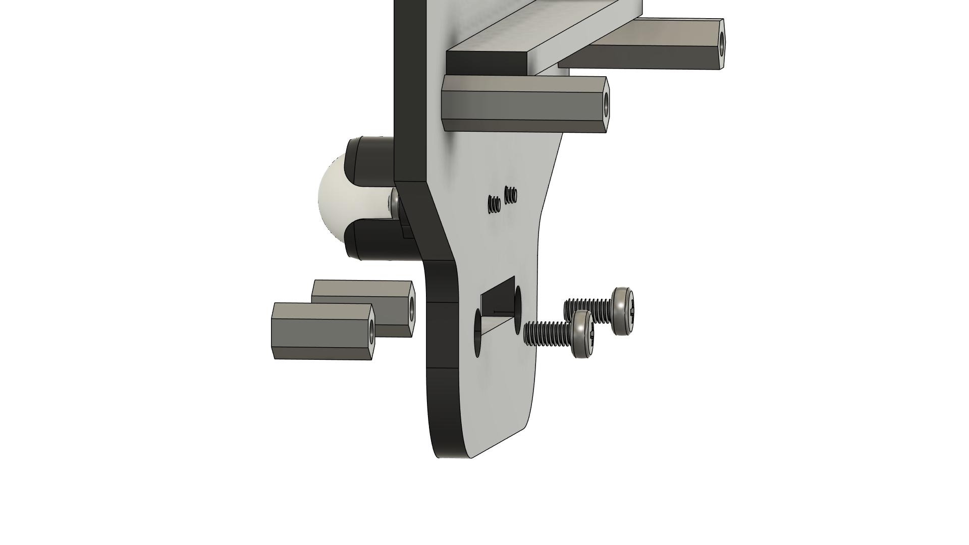 ### Instructions
1. **Identify sensor spacer mounting positions:**
- Chassis have 2 mounting holes for line sensor spacers
- These holes are at the front of the chassis
- Position should allow sensors to be centered and face downward
2. **Determine spacer configuration:**
- **Standard configuration:** 2x M3 x 10mm spacers
- Spacers create proper height for sensor positioning
- Sensors should be 3-5mm from ground when mounted
3. **Install sensor spacers:**
- Take 2x M3 x 10mm spacers
- Position at sensor mounting holes on chassis
- Insert M3 x 6mm screw from bottom of chassis
- Screw into the spacer from below
- Tighten securely
4. **Verify spacer installation:**
- All spacers should be perpendicular to chassis
- Spacers should be at same height
- Spacers should be firmly attached
- No wobbling
5. **Check sensor mounting alignment:**
- Place line sensor array on spacers (without screwing)
- Verify sensor height from ground (3-5mm optimal)
- Ensure sensors will be parallel to ground
- Adjust spacer length if needed
### Quality Check
- [ ] All sensor spacers installed (typically 2x M3 x 10mm)
- [ ] All spacers are perpendicular to chassis
- [ ] All spacers are at same height
- [ ] All spacers are tight (screws from bottom)
- [ ] Spacers do not wobble
- [ ] Sensor height will be 3-5mm from ground when mounted
**Note:** Proper sensor height is critical for line detection. The 3-5mm distance provides optimal detection while preventing scraping on uneven surfaces.
---
## Step 8: Installing Battery
### Instructions
1. **Identify sensor spacer mounting positions:**
- Chassis have 2 mounting holes for line sensor spacers
- These holes are at the front of the chassis
- Position should allow sensors to be centered and face downward
2. **Determine spacer configuration:**
- **Standard configuration:** 2x M3 x 10mm spacers
- Spacers create proper height for sensor positioning
- Sensors should be 3-5mm from ground when mounted
3. **Install sensor spacers:**
- Take 2x M3 x 10mm spacers
- Position at sensor mounting holes on chassis
- Insert M3 x 6mm screw from bottom of chassis
- Screw into the spacer from below
- Tighten securely
4. **Verify spacer installation:**
- All spacers should be perpendicular to chassis
- Spacers should be at same height
- Spacers should be firmly attached
- No wobbling
5. **Check sensor mounting alignment:**
- Place line sensor array on spacers (without screwing)
- Verify sensor height from ground (3-5mm optimal)
- Ensure sensors will be parallel to ground
- Adjust spacer length if needed
### Quality Check
- [ ] All sensor spacers installed (typically 2x M3 x 10mm)
- [ ] All spacers are perpendicular to chassis
- [ ] All spacers are at same height
- [ ] All spacers are tight (screws from bottom)
- [ ] Spacers do not wobble
- [ ] Sensor height will be 3-5mm from ground when mounted
**Note:** Proper sensor height is critical for line detection. The 3-5mm distance provides optimal detection while preventing scraping on uneven surfaces.
---
## Step 8: Installing Battery
 ### Instructions
1. **Identify battery mounting location:**
- Battery mounts in center of chassis
- Dedicated battery holder/support is provided
- Should be accessible for removal/replacement
2. **Prepare battery mounting:**
- Locate the dedicated battery support in center of chassis
- Prepare zip ties for securing battery
- Ensure battery support is clean and free of debris
3. **Position the battery:**
- Place battery in the dedicated center support
- XT60 connector should be accessible
- Battery should be centered for weight distribution
- Ensure battery is oriented correctly (check polarity markings)
4. **Secure the battery:**
- Thread zip tie(s) through battery support slots
- Wrap zip tie around battery
- Pull zip tie tight to secure battery firmly
- Trim excess zip tie length
5. **Verify battery installation:**
- Battery should be firmly mounted in center support
- Should not move when chassis is shaken
- XT60 connector is accessible
- Battery does not interfere with wheels or other components
- Zip tie is tight and secure
### Quality Check
- [ ] Battery is mounted in center dedicated support
- [ ] Battery is firmly secured with zip tie (shake test)
- [ ] XT60 connector is accessible
- [ ] Battery is centered for weight distribution
- [ ] Battery does not interfere with wheels or components
- [ ] Battery polarity markings are visible
- [ ] Zip tie is tight and trimmed
**⚠️ SAFETY:** Ensure battery is very secure. A loose battery can cause damage or fire hazard!
---
## Step 9: Mounting FRDM-MCXN947 Board
### Instructions
1. **Identify battery mounting location:**
- Battery mounts in center of chassis
- Dedicated battery holder/support is provided
- Should be accessible for removal/replacement
2. **Prepare battery mounting:**
- Locate the dedicated battery support in center of chassis
- Prepare zip ties for securing battery
- Ensure battery support is clean and free of debris
3. **Position the battery:**
- Place battery in the dedicated center support
- XT60 connector should be accessible
- Battery should be centered for weight distribution
- Ensure battery is oriented correctly (check polarity markings)
4. **Secure the battery:**
- Thread zip tie(s) through battery support slots
- Wrap zip tie around battery
- Pull zip tie tight to secure battery firmly
- Trim excess zip tie length
5. **Verify battery installation:**
- Battery should be firmly mounted in center support
- Should not move when chassis is shaken
- XT60 connector is accessible
- Battery does not interfere with wheels or other components
- Zip tie is tight and secure
### Quality Check
- [ ] Battery is mounted in center dedicated support
- [ ] Battery is firmly secured with zip tie (shake test)
- [ ] XT60 connector is accessible
- [ ] Battery is centered for weight distribution
- [ ] Battery does not interfere with wheels or components
- [ ] Battery polarity markings are visible
- [ ] Zip tie is tight and trimmed
**⚠️ SAFETY:** Ensure battery is very secure. A loose battery can cause damage or fire hazard!
---
## Step 9: Mounting FRDM-MCXN947 Board
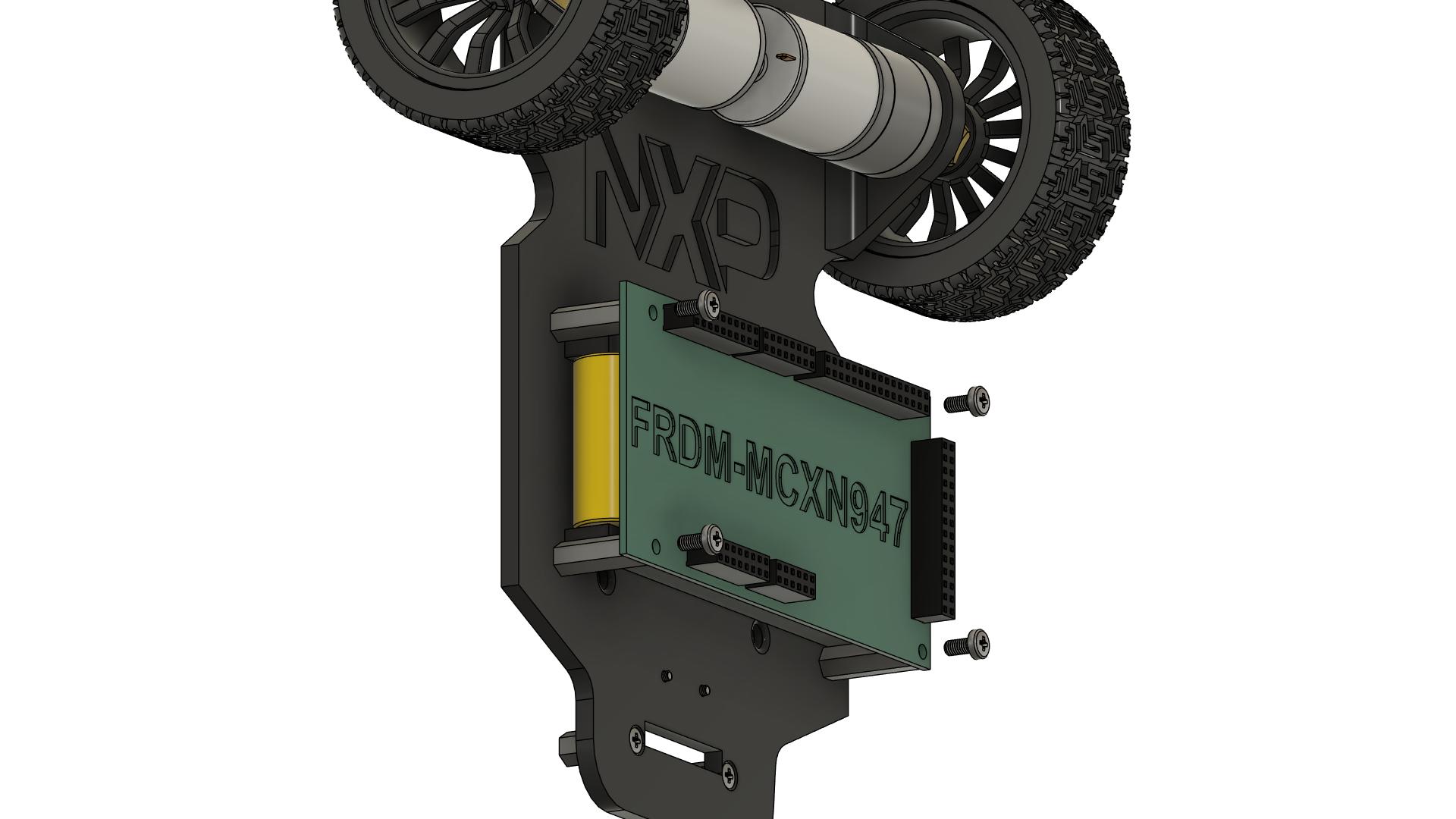 ### Instructions
1. **Prepare the FRDM-MCXN947 board:**
- Remove from anti-static packaging
- Inspect for any damage
- Identify the 4 mounting holes
2. **Position the board:**
- Align the board mounting holes with the spacers
- USB connector should be accessible (usually toward rear or side)
- Ensure correct orientation
3. **Place board on spacers:**
- Carefully lower the board onto the spacers
- All 4 mounting holes should align
- Do not force - if holes don't align, check spacer positions
4. **Secure the board:**
- Insert 4x M3 x 6mm screws through board holes
- Screw into the top of each spacer
- Tighten in a cross pattern (opposite corners)
- Do not over-tighten (can crack the PCB)
5. **Verify board installation:**
- Board should be stable and level (or at designed angle)
- No wobbling
- USB connector is accessible
- All mounting screws are snug
### Quality Check
- [ ] FRDM-MCXN947 board is mounted on spacers
- [ ] All 4 mounting screws are installed and tight
- [ ] Board is stable with no wobbling
- [ ] USB connector is accessible
- [ ] Board is at correct orientation
- [ ] No stress on the PCB
**⚠️ CAUTION:** Do not over-tighten screws - this can crack the PCB!
---
## Step 10: Connecting NXPCUP Shield
### Instructions
1. **Prepare the FRDM-MCXN947 board:**
- Remove from anti-static packaging
- Inspect for any damage
- Identify the 4 mounting holes
2. **Position the board:**
- Align the board mounting holes with the spacers
- USB connector should be accessible (usually toward rear or side)
- Ensure correct orientation
3. **Place board on spacers:**
- Carefully lower the board onto the spacers
- All 4 mounting holes should align
- Do not force - if holes don't align, check spacer positions
4. **Secure the board:**
- Insert 4x M3 x 6mm screws through board holes
- Screw into the top of each spacer
- Tighten in a cross pattern (opposite corners)
- Do not over-tighten (can crack the PCB)
5. **Verify board installation:**
- Board should be stable and level (or at designed angle)
- No wobbling
- USB connector is accessible
- All mounting screws are snug
### Quality Check
- [ ] FRDM-MCXN947 board is mounted on spacers
- [ ] All 4 mounting screws are installed and tight
- [ ] Board is stable with no wobbling
- [ ] USB connector is accessible
- [ ] Board is at correct orientation
- [ ] No stress on the PCB
**⚠️ CAUTION:** Do not over-tighten screws - this can crack the PCB!
---
## Step 10: Connecting NXPCUP Shield
 ### Instructions
1. **Prepare the shield:**
- Take the assembled NXPCUP-Shield
- Inspect all header connectors
- Ensure no bent pins
2. **Identify mating connectors:**
- Shield has female headers (J1, J2, J5, J6)
- FRDM-MCXN947 has corresponding male headers
- Check alignment before connecting
3. **Align the shield:**
- Hold shield above the FRDM board
- Align all header connectors
- Ensure correct orientation (usually marked on PCB)
4. **Connect the shield:**
- Lower the shield carefully
- All header pins should start entering the sockets
- **Do not force!** If pins don't align, lift and realign
5. **Press shield down:**
- Apply even pressure across the shield
- Press down until shield is fully seated
- All connectors should be fully mated
6. **Verify connection:**
- Shield should be parallel to FRDM board
- No gaps between shield and board headers
- No bent pins visible
### Quality Check
- [ ] Shield is properly aligned with FRDM board
- [ ] All header connectors are fully mated
- [ ] No bent pins
- [ ] Shield is parallel to FRDM board
- [ ] Shield is stable and does not wobble
- [ ] All connectors (J1, J2, J5, J6) are connected
**⚠️ IMPORTANT:** Bent pins can cause malfunction or damage. Be very careful during this step!
---
## Step 11: Mounting Line Sensors
### Instructions
1. **Prepare the shield:**
- Take the assembled NXPCUP-Shield
- Inspect all header connectors
- Ensure no bent pins
2. **Identify mating connectors:**
- Shield has female headers (J1, J2, J5, J6)
- FRDM-MCXN947 has corresponding male headers
- Check alignment before connecting
3. **Align the shield:**
- Hold shield above the FRDM board
- Align all header connectors
- Ensure correct orientation (usually marked on PCB)
4. **Connect the shield:**
- Lower the shield carefully
- All header pins should start entering the sockets
- **Do not force!** If pins don't align, lift and realign
5. **Press shield down:**
- Apply even pressure across the shield
- Press down until shield is fully seated
- All connectors should be fully mated
6. **Verify connection:**
- Shield should be parallel to FRDM board
- No gaps between shield and board headers
- No bent pins visible
### Quality Check
- [ ] Shield is properly aligned with FRDM board
- [ ] All header connectors are fully mated
- [ ] No bent pins
- [ ] Shield is parallel to FRDM board
- [ ] Shield is stable and does not wobble
- [ ] All connectors (J1, J2, J5, J6) are connected
**⚠️ IMPORTANT:** Bent pins can cause malfunction or damage. Be very careful during this step!
---
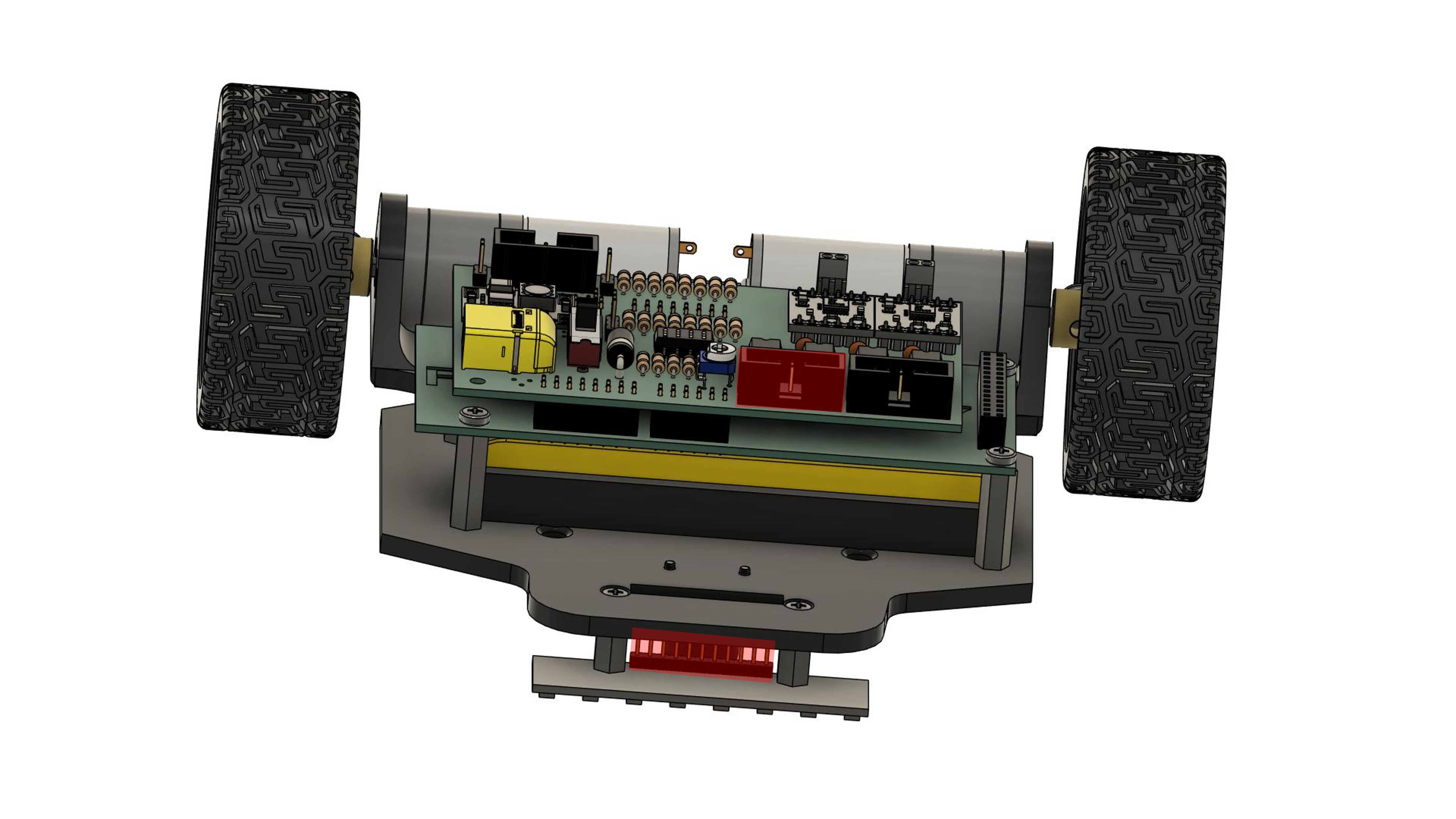
## Step 11: Mounting Line Sensors
 ### Instructions
1. **Identify sensor mounting position:**
- Sensors mount at front of chassis (or rear, depending on design)
- Should be centered left-to-right
- Should face downward toward the track
2. **Prepare the sensor array:**
- Line sensor array typically has multiple IR sensors
- Check that all sensors are clean
- Identify mounting holes on sensor PCB
3. **Position the sensors:**
- Place sensor array on the spacers installed in Step 7
- Sensors should point downward
- Align mounting holes with spacer tops
- Ensure sensors are perpendicular to driving direction
4. **Secure the sensors:**
- Use 2x M3 x 6mm screws
- Insert screws through sensor PCB holes
- Screw into the top of each spacer
- Tighten evenly in a cross pattern
5. **Check sensor height:**
- **Optimal distance:** 3-5mm from ground to sensor face
- Too close: may scrape on uneven surfaces
- Too far: reduced sensitivity
- Adjust spacer length if needed (return to Step 7)
6. **Verify sensor orientation:**
- Sensors should be parallel to ground
- Sensors should be centered on chassis
- All sensors should be at same height
### Quality Check
- [ ] Line sensors are mounted securely on spacers
- [ ] Sensors are 3-5mm from ground
- [ ] Sensors are parallel to ground
- [ ] Sensors are centered on chassis
- [ ] Sensors face downward
- [ ] All mounting screws are tight
- [ ] Sensors do not interfere with wheels or ball caster
**Note:** Sensor height is critical for line detection. Test on actual track and adjust if needed.
---
## Step 12: Connecting Motors to Shield
### Instructions
1. **Identify sensor mounting position:**
- Sensors mount at front of chassis (or rear, depending on design)
- Should be centered left-to-right
- Should face downward toward the track
2. **Prepare the sensor array:**
- Line sensor array typically has multiple IR sensors
- Check that all sensors are clean
- Identify mounting holes on sensor PCB
3. **Position the sensors:**
- Place sensor array on the spacers installed in Step 7
- Sensors should point downward
- Align mounting holes with spacer tops
- Ensure sensors are perpendicular to driving direction
4. **Secure the sensors:**
- Use 2x M3 x 6mm screws
- Insert screws through sensor PCB holes
- Screw into the top of each spacer
- Tighten evenly in a cross pattern
5. **Check sensor height:**
- **Optimal distance:** 3-5mm from ground to sensor face
- Too close: may scrape on uneven surfaces
- Too far: reduced sensitivity
- Adjust spacer length if needed (return to Step 7)
6. **Verify sensor orientation:**
- Sensors should be parallel to ground
- Sensors should be centered on chassis
- All sensors should be at same height
### Quality Check
- [ ] Line sensors are mounted securely on spacers
- [ ] Sensors are 3-5mm from ground
- [ ] Sensors are parallel to ground
- [ ] Sensors are centered on chassis
- [ ] Sensors face downward
- [ ] All mounting screws are tight
- [ ] Sensors do not interfere with wheels or ball caster
**Note:** Sensor height is critical for line detection. Test on actual track and adjust if needed.
---
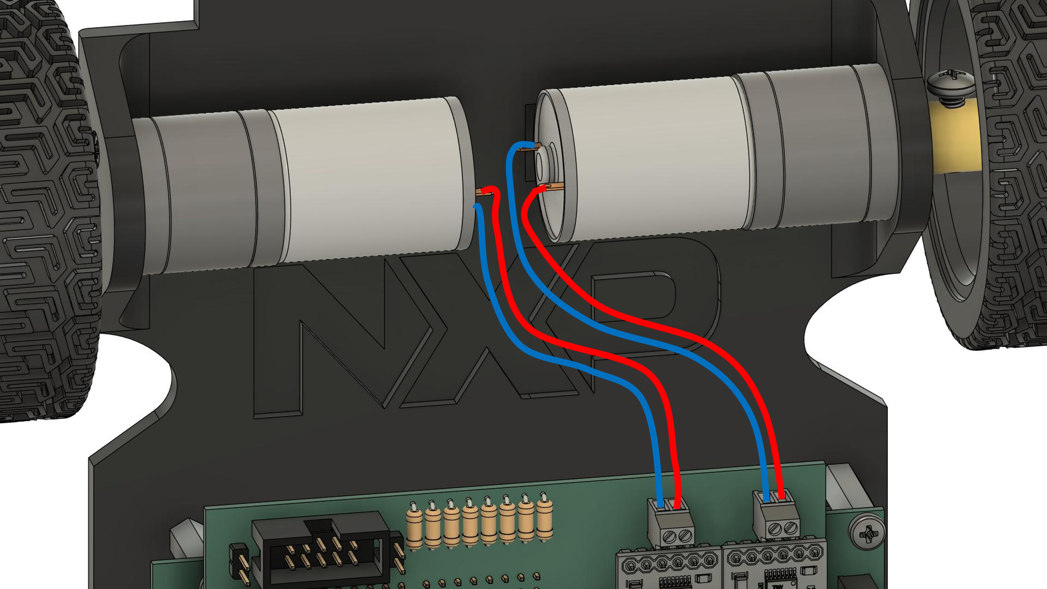
## Step 12: Connecting Motors to Shield
 ### Instructions
1. **Identify motor terminals:**
- Each motor has 2 wires (usually red and black, or both same color)
- Left motor wires
- Right motor wires
2. **Identify shield motor terminals:**
- **J11:** Motor 1 terminal (usually left motor)
- **J12:** Motor 2 terminal (usually right motor)
- Each terminal has 2 positions
3. **Prepare motor wires:**
- If motors don't have wires pre-attached, solder wires to motor terminals
- Use appropriate gauge wire (typically 22-24 AWG)
- Solder one wire to each motor terminal
- Ensure good solder joints (shiny, not cold/dull)
- If wires are too long, consider shortening (leave some slack)
- Strip wire ends if needed (about 5mm)
- Twist stranded wire ends to prevent fraying
4. **Connect left motor to J11:**
- Loosen both screws on J11 terminal
- Insert one motor wire into first position
- Insert other motor wire into second position
- Tighten both screws firmly
- Tug gently on wires to ensure secure connection
5. **Connect right motor to J12:**
- Same procedure as J11
- Loosen screws, insert wires, tighten screws
6. **Cable management:**
- Route motor wires neatly
- Avoid wires near wheels or moving parts
- Use cable ties to secure wires to chassis
- Leave some slack for movement/vibration
### Quality Check
- [ ] Wires are soldered securely to motor terminals
- [ ] Solder joints are clean and shiny
- [ ] Left motor connected to J11
- [ ] Right motor connected to J12
- [ ] All 4 terminal screws are tight
- [ ] Wires are secure (gentle tug test)
- [ ] Wires are routed away from wheels
- [ ] Wires are secured with cable ties
- [ ] Some slack in wires for vibration
**Note:** Motor polarity determines rotation direction. If a motor runs backward during testing, simply swap its two wires at the terminal.
---
## Step 13: Connecting Ribbon Cable
### Instructions
1. **Identify motor terminals:**
- Each motor has 2 wires (usually red and black, or both same color)
- Left motor wires
- Right motor wires
2. **Identify shield motor terminals:**
- **J11:** Motor 1 terminal (usually left motor)
- **J12:** Motor 2 terminal (usually right motor)
- Each terminal has 2 positions
3. **Prepare motor wires:**
- If motors don't have wires pre-attached, solder wires to motor terminals
- Use appropriate gauge wire (typically 22-24 AWG)
- Solder one wire to each motor terminal
- Ensure good solder joints (shiny, not cold/dull)
- If wires are too long, consider shortening (leave some slack)
- Strip wire ends if needed (about 5mm)
- Twist stranded wire ends to prevent fraying
4. **Connect left motor to J11:**
- Loosen both screws on J11 terminal
- Insert one motor wire into first position
- Insert other motor wire into second position
- Tighten both screws firmly
- Tug gently on wires to ensure secure connection
5. **Connect right motor to J12:**
- Same procedure as J11
- Loosen screws, insert wires, tighten screws
6. **Cable management:**
- Route motor wires neatly
- Avoid wires near wheels or moving parts
- Use cable ties to secure wires to chassis
- Leave some slack for movement/vibration
### Quality Check
- [ ] Wires are soldered securely to motor terminals
- [ ] Solder joints are clean and shiny
- [ ] Left motor connected to J11
- [ ] Right motor connected to J12
- [ ] All 4 terminal screws are tight
- [ ] Wires are secure (gentle tug test)
- [ ] Wires are routed away from wheels
- [ ] Wires are secured with cable ties
- [ ] Some slack in wires for vibration
**Note:** Motor polarity determines rotation direction. If a motor runs backward during testing, simply swap its two wires at the terminal.
---
## Step 13: Connecting Ribbon Cable
 ### Instructions
1. **Identify connectors:**
- **Line sensor connector:** Usually on sensor PCB
- **Shield connector J1:** 2x10 pin header on shield
2. **Prepare ribbon cable:**
- Identify pin 1 on both ends (usually marked with red stripe or arrow)
- Check cable length - should reach from sensors to shield
- Ensure cable is not damaged
3. **Connect to line sensors:**
- Align ribbon cable connector with sensor connector
- **⚠️ Match pin 1 markings! (Pin 1 is separated from the other pins in the socket)**
- Press connector firmly until fully seated
- Some connectors have a latch - ensure it clicks
4. **Route the cable:**
- Route cable from sensors to shield
- Avoid sharp bends
- Keep cable away from wheels and moving parts
- Leave some slack for vibration
5. **Connect to shield J1:**
- Align ribbon cable connector with J1 on shield
- **⚠️ Match pin 1 markings!**
- Press connector firmly until fully seated
6. **Secure the cable:**
- Use cable ties to secure ribbon cable to chassis
- Ensure cable cannot get caught in wheels
- Do not over-tighten cable ties (can damage ribbon cable)
### Quality Check
- [ ] Ribbon cable connected to line sensors
- [ ] Ribbon cable connected to shield J1
- [ ] Pin 1 orientation is correct on both ends
- [ ] Both connectors are fully seated
- [ ] Cable is routed neatly
- [ ] Cable is secured with cable ties
- [ ] Cable has some slack
- [ ] Cable cannot interfere with wheels or moving parts
**⚠️ CRITICAL:** Incorrect pin 1 orientation can damage the sensors or shield!
---
## Step 13: Final Checks Before Power-On
### Instructions
1. **Identify connectors:**
- **Line sensor connector:** Usually on sensor PCB
- **Shield connector J1:** 2x10 pin header on shield
2. **Prepare ribbon cable:**
- Identify pin 1 on both ends (usually marked with red stripe or arrow)
- Check cable length - should reach from sensors to shield
- Ensure cable is not damaged
3. **Connect to line sensors:**
- Align ribbon cable connector with sensor connector
- **⚠️ Match pin 1 markings! (Pin 1 is separated from the other pins in the socket)**
- Press connector firmly until fully seated
- Some connectors have a latch - ensure it clicks
4. **Route the cable:**
- Route cable from sensors to shield
- Avoid sharp bends
- Keep cable away from wheels and moving parts
- Leave some slack for vibration
5. **Connect to shield J1:**
- Align ribbon cable connector with J1 on shield
- **⚠️ Match pin 1 markings!**
- Press connector firmly until fully seated
6. **Secure the cable:**
- Use cable ties to secure ribbon cable to chassis
- Ensure cable cannot get caught in wheels
- Do not over-tighten cable ties (can damage ribbon cable)
### Quality Check
- [ ] Ribbon cable connected to line sensors
- [ ] Ribbon cable connected to shield J1
- [ ] Pin 1 orientation is correct on both ends
- [ ] Both connectors are fully seated
- [ ] Cable is routed neatly
- [ ] Cable is secured with cable ties
- [ ] Cable has some slack
- [ ] Cable cannot interfere with wheels or moving parts
**⚠️ CRITICAL:** Incorrect pin 1 orientation can damage the sensors or shield!
---
## Step 13: Final Checks Before Power-On
 ### Mechanical Checks
- [ ] All screws are tight (motors, wheels, ball caster, boards, sensors)
- [ ] Wheels rotate freely without rubbing
- [ ] Ball caster rolls freely in all directions
- [ ] No loose components
- [ ] Chassis is stable
### Electrical Checks
- [ ] All connectors are fully seated:
- [ ] Shield to FRDM board (J1, J2, J5, J6)
- [ ] Motors to shield (J11, J12)
- [ ] Line sensors ribbon cable (both ends)
- [ ] Battery to shield (J10)
- [ ] No visible short circuits or solder bridges
- [ ] All wires are secured and routed properly
- [ ] No wires near moving parts (wheels)
### Component Orientation Checks
- [ ] Shield is correctly oriented on FRDM board
- [ ] LM339 ICs have correct orientation (notch alignment)
- [ ] Diode D1 has correct polarity
- [ ] XT60 connector has correct polarity
- [ ] Ribbon cable pin 1 is correct on both ends
### Safety Checks
- [ ] Battery is firmly secured
- [ ] Switch S1 is in OFF position
- [ ] Work area is clear of metal objects
- [ ] Fire extinguisher nearby (recommended for LiPo batteries)
- [ ] No damaged wires or components
### Documentation
- [ ] Take photos of completed assembly (top, bottom, sides)
- [ ] Note any modifications or issues
- [ ] Record battery voltage before first use
---
## Step 15: First Power-On Test
### Pre-Power Checks
1. **Final visual inspection:**
- Look for any obvious problems
- Check all connections one more time
- Ensure nothing is loose
2. **Prepare for test:**
- Place car on a non-conductive surface
- Elevate car so wheels don't touch surface (use a stand or blocks)
- Have multimeter ready
- Be ready to quickly turn off power if needed
### Power-On Procedure
**⚠️ IMPORTANT:** Keep your hand on switch S1 to quickly turn off if needed!
1. **Turn on power:**
- Switch S1 to ON position
- Observe immediately
2. **Check for problems (first 5 seconds):**
- [ ] **No smoke** → If smoke appears, turn OFF immediately!
- [ ] **No burning smell** → If smell detected, turn OFF immediately!
- [ ] **No excessive heat** → Touch components gently, turn OFF if very hot
- [ ] **No sparks** → Turn OFF if sparks appear
- [ ] **No unusual sounds** → Turn OFF if buzzing or popping sounds
3. **Check LEDs (if no problems detected):**
- [ ] Power LED on shield is ON
- [ ] Power LED on FRDM-MCXN947 is ON
- [ ] Any status LEDs show expected state
4. **Measure voltages with multimeter:**
- [ ] Battery voltage at XT60: ~7.4V (or current charge level)
- [ ] 5V rail on shield: 5.0V ±0.25V
- [ ] 3.3V on FRDM board: 3.3V ±0.15V
5. **Check components:**
- [ ] Shield components are not excessively hot
- [ ] DC-DC converter (U1) is slightly warm (normal)
- [ ] Motor drivers (U2, U3) are cool or slightly warm
- [ ] FRDM board is cool
6. **Turn off power:**
- Switch S1 to OFF position
- Wait 10 seconds
- Check components for any residual heat
### If Everything is OK
**Congratulations!** Your NXP Cup car hardware is assembled and powered correctly!
### Quality Check
- [ ] Power-on successful with no issues
- [ ] All LEDs functioning
- [ ] Voltage measurements correct
- [ ] No excessive heat
- [ ] No smoke or unusual smells
---
## Assembly Complete! ✓
Your NXP Cup car is now fully assembled and ready for programming!
---
## Safety Reminders
### LiPo Battery Safety
- ⚠️ **Never** short circuit battery terminals
- ⚠️ **Never** puncture or damage battery
- ⚠️ **Never** charge unattended
- ⚠️ **Never** exceed 4.2V per cell when charging
- ⚠️ **Always** use LiPo-specific charger
- ⚠️ **Always** store in fireproof bag
- ⚠️ **Always** dispose of damaged batteries properly
### Operational Safety
- ⚠️ Keep fingers away from moving wheels
- ⚠️ Ensure car cannot fall off table during testing
- ⚠️ Test in safe area away from obstacles
- ⚠️ Have emergency stop method ready
- ⚠️ Wear safety glasses during assembly/testing
### Electrical Safety
- ⚠️ Always turn off power before making connections
- ⚠️ Never work on powered circuits
- ⚠️ Check polarity before connecting battery
- ⚠️ Disconnect battery when not in use
- ⚠️ Keep liquids away from electronics
---
**Next Steps:**
- [Programming Guide →](programming.md)
[← Shield Assembly](shield-assembly.md) | [← Back to Main](../tutorial.md)
### Mechanical Checks
- [ ] All screws are tight (motors, wheels, ball caster, boards, sensors)
- [ ] Wheels rotate freely without rubbing
- [ ] Ball caster rolls freely in all directions
- [ ] No loose components
- [ ] Chassis is stable
### Electrical Checks
- [ ] All connectors are fully seated:
- [ ] Shield to FRDM board (J1, J2, J5, J6)
- [ ] Motors to shield (J11, J12)
- [ ] Line sensors ribbon cable (both ends)
- [ ] Battery to shield (J10)
- [ ] No visible short circuits or solder bridges
- [ ] All wires are secured and routed properly
- [ ] No wires near moving parts (wheels)
### Component Orientation Checks
- [ ] Shield is correctly oriented on FRDM board
- [ ] LM339 ICs have correct orientation (notch alignment)
- [ ] Diode D1 has correct polarity
- [ ] XT60 connector has correct polarity
- [ ] Ribbon cable pin 1 is correct on both ends
### Safety Checks
- [ ] Battery is firmly secured
- [ ] Switch S1 is in OFF position
- [ ] Work area is clear of metal objects
- [ ] Fire extinguisher nearby (recommended for LiPo batteries)
- [ ] No damaged wires or components
### Documentation
- [ ] Take photos of completed assembly (top, bottom, sides)
- [ ] Note any modifications or issues
- [ ] Record battery voltage before first use
---
## Step 15: First Power-On Test
### Pre-Power Checks
1. **Final visual inspection:**
- Look for any obvious problems
- Check all connections one more time
- Ensure nothing is loose
2. **Prepare for test:**
- Place car on a non-conductive surface
- Elevate car so wheels don't touch surface (use a stand or blocks)
- Have multimeter ready
- Be ready to quickly turn off power if needed
### Power-On Procedure
**⚠️ IMPORTANT:** Keep your hand on switch S1 to quickly turn off if needed!
1. **Turn on power:**
- Switch S1 to ON position
- Observe immediately
2. **Check for problems (first 5 seconds):**
- [ ] **No smoke** → If smoke appears, turn OFF immediately!
- [ ] **No burning smell** → If smell detected, turn OFF immediately!
- [ ] **No excessive heat** → Touch components gently, turn OFF if very hot
- [ ] **No sparks** → Turn OFF if sparks appear
- [ ] **No unusual sounds** → Turn OFF if buzzing or popping sounds
3. **Check LEDs (if no problems detected):**
- [ ] Power LED on shield is ON
- [ ] Power LED on FRDM-MCXN947 is ON
- [ ] Any status LEDs show expected state
4. **Measure voltages with multimeter:**
- [ ] Battery voltage at XT60: ~7.4V (or current charge level)
- [ ] 5V rail on shield: 5.0V ±0.25V
- [ ] 3.3V on FRDM board: 3.3V ±0.15V
5. **Check components:**
- [ ] Shield components are not excessively hot
- [ ] DC-DC converter (U1) is slightly warm (normal)
- [ ] Motor drivers (U2, U3) are cool or slightly warm
- [ ] FRDM board is cool
6. **Turn off power:**
- Switch S1 to OFF position
- Wait 10 seconds
- Check components for any residual heat
### If Everything is OK
**Congratulations!** Your NXP Cup car hardware is assembled and powered correctly!
### Quality Check
- [ ] Power-on successful with no issues
- [ ] All LEDs functioning
- [ ] Voltage measurements correct
- [ ] No excessive heat
- [ ] No smoke or unusual smells
---
## Assembly Complete! ✓
Your NXP Cup car is now fully assembled and ready for programming!
---
## Safety Reminders
### LiPo Battery Safety
- ⚠️ **Never** short circuit battery terminals
- ⚠️ **Never** puncture or damage battery
- ⚠️ **Never** charge unattended
- ⚠️ **Never** exceed 4.2V per cell when charging
- ⚠️ **Always** use LiPo-specific charger
- ⚠️ **Always** store in fireproof bag
- ⚠️ **Always** dispose of damaged batteries properly
### Operational Safety
- ⚠️ Keep fingers away from moving wheels
- ⚠️ Ensure car cannot fall off table during testing
- ⚠️ Test in safe area away from obstacles
- ⚠️ Have emergency stop method ready
- ⚠️ Wear safety glasses during assembly/testing
### Electrical Safety
- ⚠️ Always turn off power before making connections
- ⚠️ Never work on powered circuits
- ⚠️ Check polarity before connecting battery
- ⚠️ Disconnect battery when not in use
- ⚠️ Keep liquids away from electronics
---
**Next Steps:**
- [Programming Guide →](programming.md)
[← Shield Assembly](shield-assembly.md) | [← Back to Main](../tutorial.md)