# Programming Guide for Line Follower Robot
[← Back to Main](../tutorial.md)
## Table of Contents
1. [Setup & First Steps](#step-1-setup-and-first-steps)
2. [LED Blinky Demo](#step-2-led-blinky-demo)
3. [PWM Control for Motors](#step-3-pwm-control-for-motors) *(Coming soon)*
4. [Reading Line Sensors](#step-4-reading-line-sensors) *(Coming soon)*
5. [Differential Drive Control](#step-5-differential-drive-control) *(Coming soon)*
---
## Step 1: Setup and First Steps
### Get Started with the Board
The FRDM-MCXN947 board comes pre-programmed with an LED blinky demo. This built-in example serves as a quick sanity check to confirm that the board is functioning correctly right out of the box.
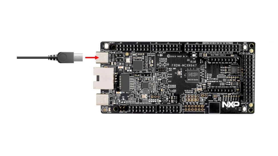
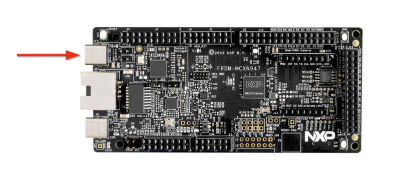
#### Plug in the Board
Connect a USB Type-C cable from connector **J17** on the FRDM-MCXN947 board to your host computer or a USB power supply. This will power up the board and automatically run the pre-programmed demo application.
**What to expect:**
The onboard RGB LED should start blinking at a steady rhythm. This indicates that the board is functioning correctly and the demo firmware is running as expected.
---
### Get Required Tools
To access the tools required for this project, you'll need to create an NXP account. You can use either your personal or student email address.
Create your account by [visiting this page](https://www.nxp.com/mynxp/home).
---
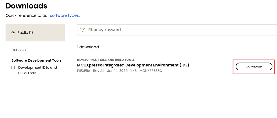
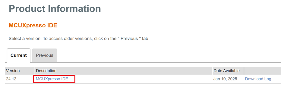
#### Get MCUXpresso IDE
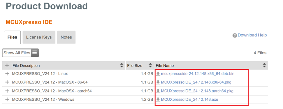
Download the latest version of the MCUXpresso IDE from the [NXP website](https://www.nxp.com/design/design-center/software/development-software/mcuxpresso-software-and-tools-/mcuxpresso-integrated-development-environment-ide:MCUXpresso-IDE?&tid=vanMCUXPRESSO/IDE).
Make sure to select the installer that matches your operating system (Windows, Linux, or macOS).
---
#### Install MCUXpresso IDE
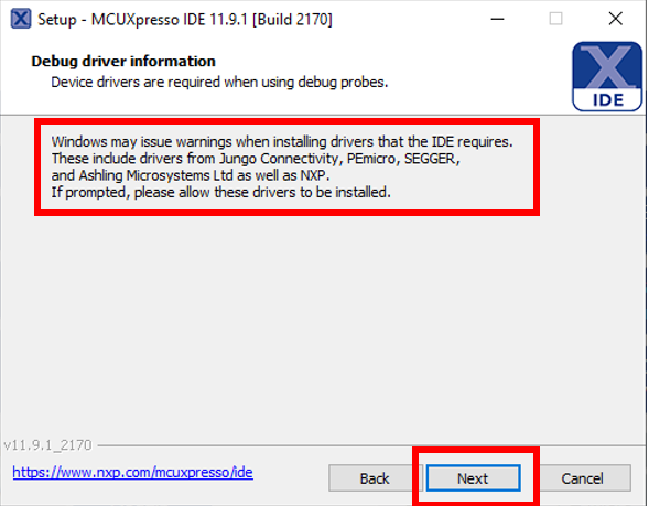
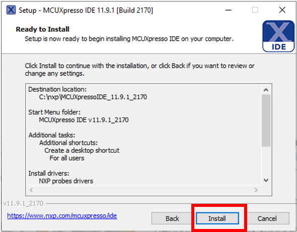
Continue clicking "Next" until you reach the install window.
In this step, you may be prompted to install additional drivers during the installation process. Allow these to be installed.
---
#### Install SDK for FRDM-MCXN947
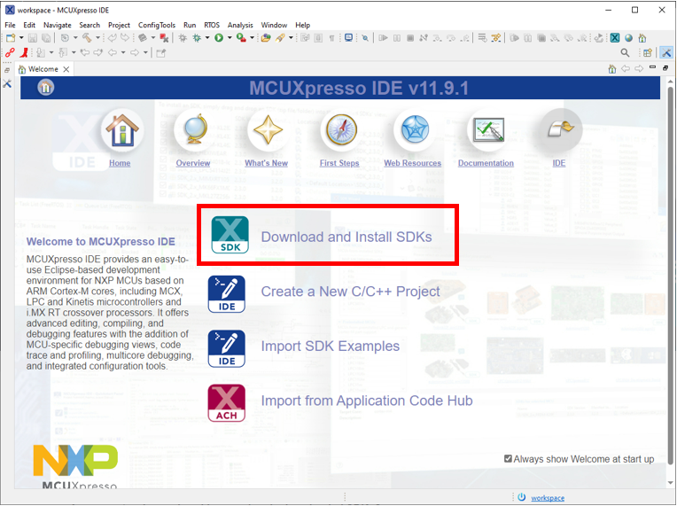
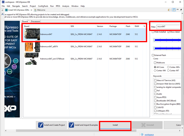
Now launch the MCUXpresso IDE and install the SDK. On the IDE Welcome page, click **"Download and Install SDKs"**.
Search for **"mcxn947"** and click **"Install"**.
---
#### Get MCUXpresso Config Tools
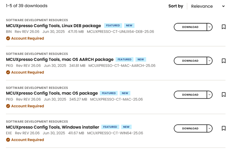
Next, download the [MCUXpresso Config Tools](https://www.nxp.com/design/design-center/software/development-software/mcuxpresso-software-and-tools-/mcuxpresso-config-tools-pins-clocks-and-peripherals:MCUXpresso-Config-Tools?tab=Design_Tools_Tab), which is a suite of utilities that simplifies the configuration of pins, peripherals, and clocks for your project.
Get the correct installation for the machine you are using.
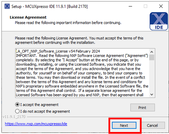
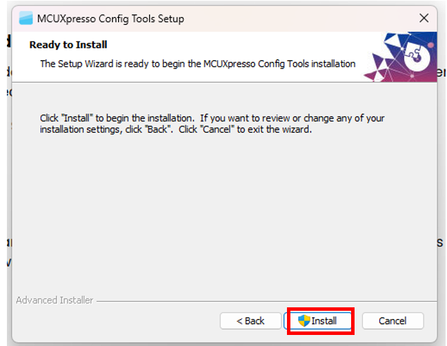
Accept the "License Agreement" and press "Next" until you get to the installation window.
**Congratulations!** You have successfully tested the board and installed the required tools!
---
## Step 2: LED Blinky Demo
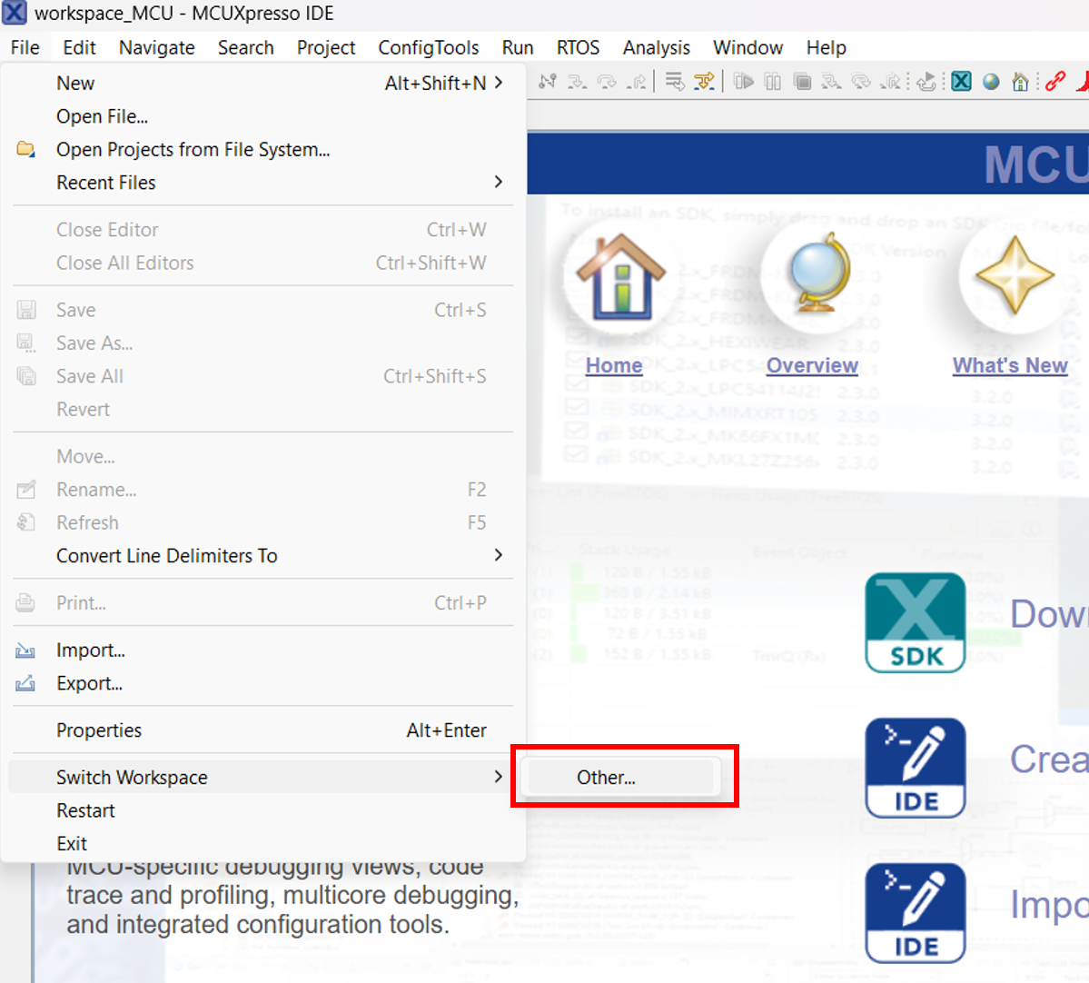
### Create a Workspace
First, let's create a workspace folder. Launch the IDE and select where you want to locate your workspace. Keep in mind that switching workspaces restarts the IDE.
---
### Import the LED Blinky Example
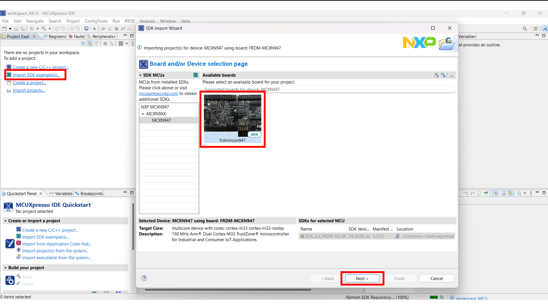
Close the Welcome page and select **"Import SDK example(s)..."**. Select the correct MCXN947 board and press **"Next"**.
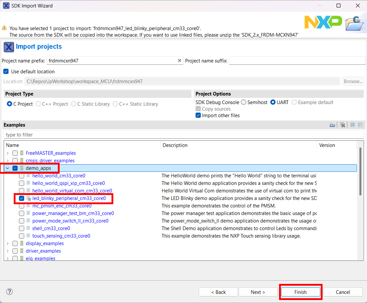
From the Import Wizard, expand the **demo_apps** section and select the **"led_blinky"** application. Then press **"Finish"** and wait for the project to open.
---
### Explore the Project
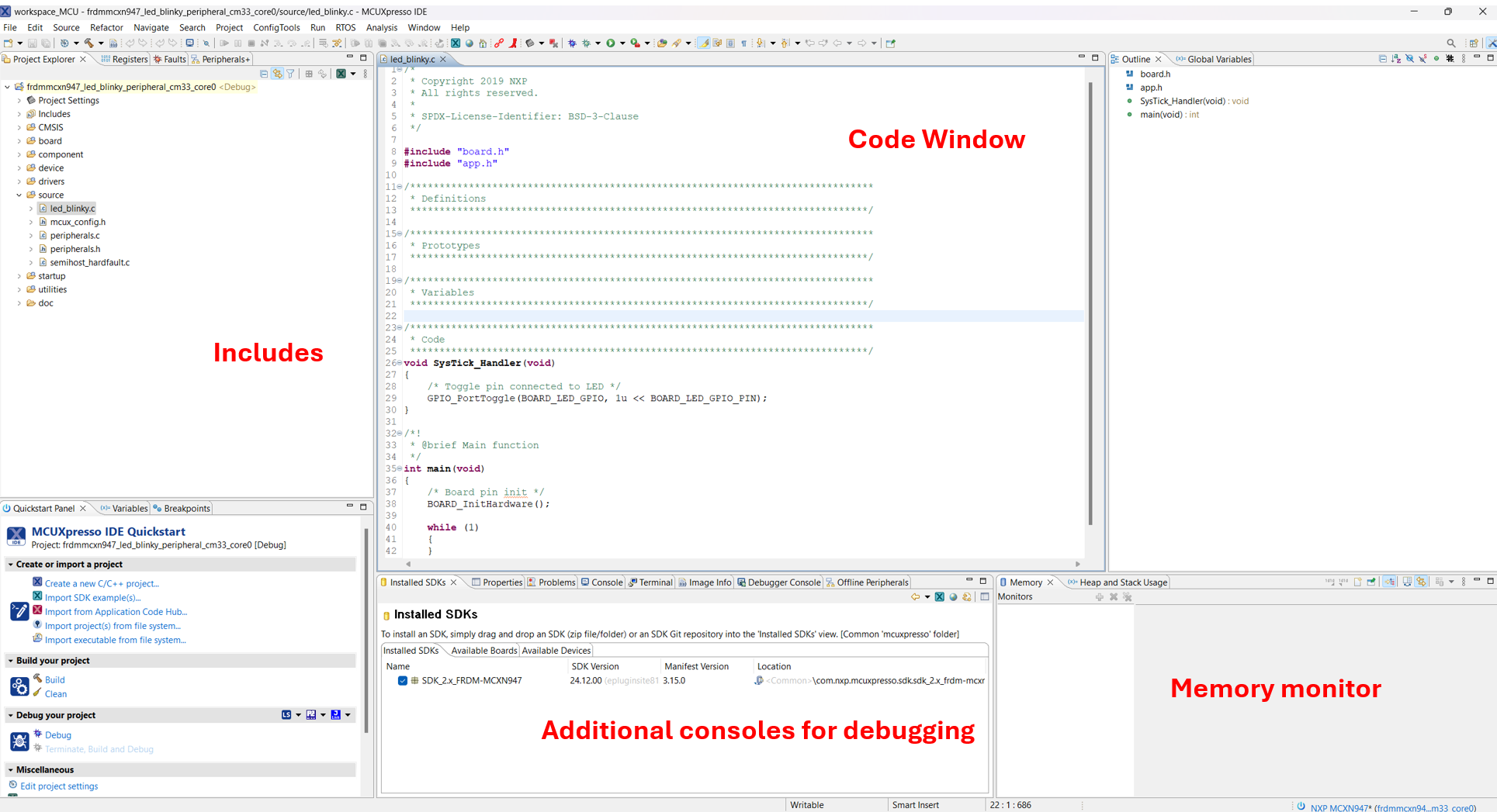
You can see that the project window is split into several sections.
---
### Understanding the Code
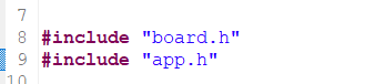
Let's take a look at the code. The top part contains the include files present in the project tree and visible in the Project Explorer tab.
---
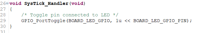
#### SysTick_Handler Function
The next section is the **SysTick_Handler** function that toggles the red LED on the board.
This function is periodically called to switch the LED ON and OFF.
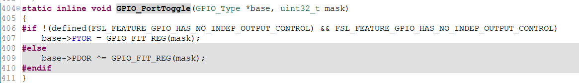
**Ctrl + Click** on the `GPIO_PortToggle` function to open the declaration in the `fsl_gpio.h` header file.
---
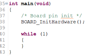
#### Main Function
The main function starts by calling the initialization function.
---
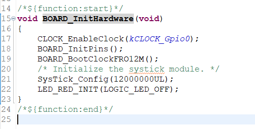
#### Hardware Initialization
The initialization function can be found in the `hardware_init.c` file.
This function:
- Enables a clock
- Initializes the board pins
- `BOARD_BootClockFRO12M()` sets the clock frequency to 12 MHz
- `SysTick_Config(12000000UL)` sets a counter with a value of 12,000,000 that makes the LED blink once per second
**Note:** Changing the counter value will increase/decrease the blinking frequency, but it needs to be slow enough for the human eye to notice it.
`LED_RED_INIT(LOGIC_LED_OFF)` calls `GPIO_PinWrite()` that changes the output of the GPIO (in this case to the OFF state).
---
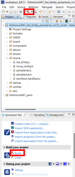
### Build the Project
To build a project, select it and then either click on the **"Build"** icon in the shortcuts or click **"Build"** in the Quickstart Panel.
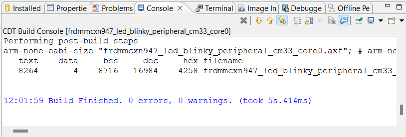
The project should finish the build without any errors or warnings in the console.
---
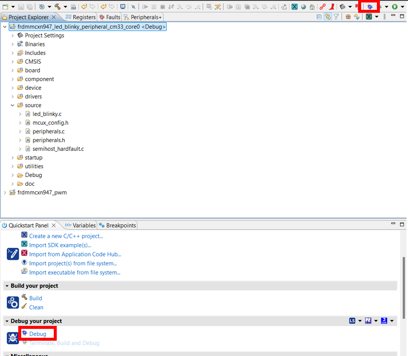
### Download to Board
Make sure your board is connected to the computer through the **J17 'MCU-LINK'** port.
Download the application to your board by either clicking on the **"Debug"** icon or clicking **"Debug"** in the Quickstart Panel.
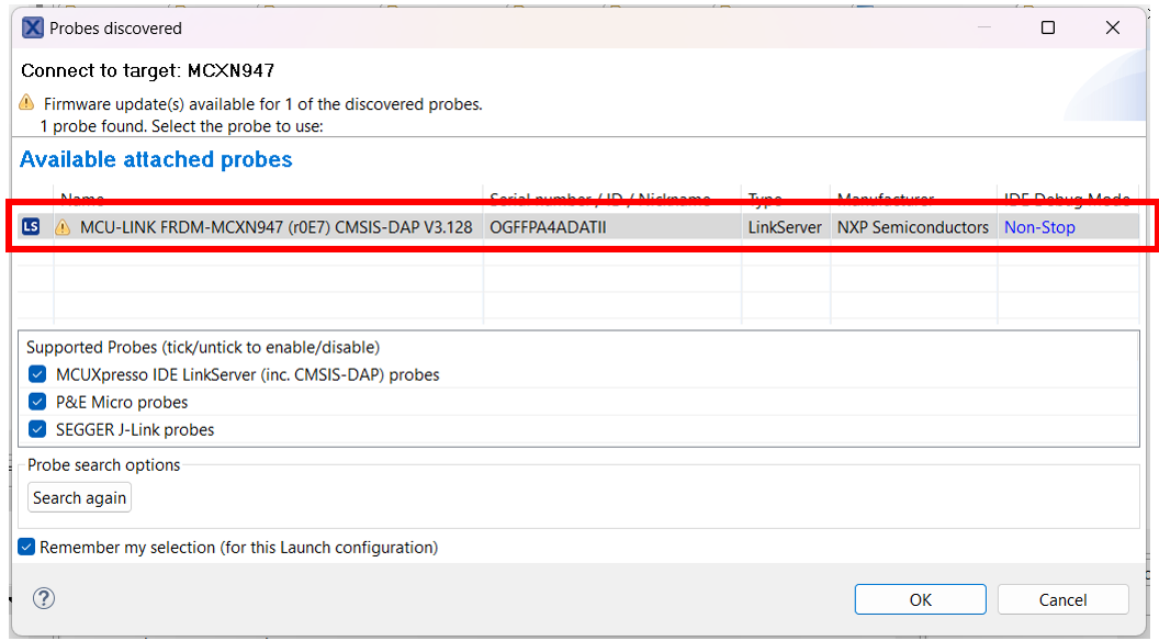
In the next window, select the **MCU-LINK CMSIS-DAP** debug probe.
---
### Run the Application
To run the application, press the **"Run"** icon.
**Congratulations!** You have successfully built and run your first program on the FRDM-MCXN947!
---
---
## Step 3: Import Line Follower Project
### Download the Project Archive
To begin working on the line follower application, you'll need to import the existing project into MCUXpresso IDE.
**Download the project archive:**
📦 Download NXP Line Follower Project (ZIP)
**Note:** Make sure you have the project archive file (`.zip`) ready before proceeding.
---
### Import the Project into MCUXpresso IDE
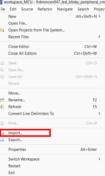
Inside the MCUXpresso IDE, go to **File** and choose the **Import** option.
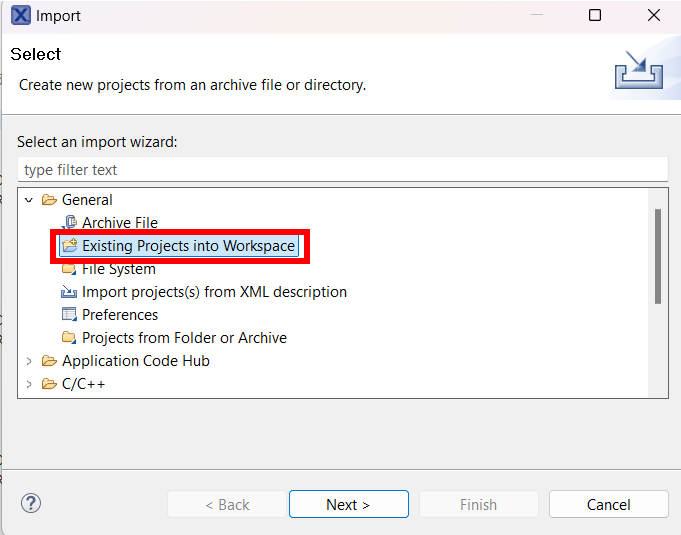
In the popup window that will open, expand the **General** menu and choose the **"Existing Projects into Workspace"** option, then click **"Next"**.
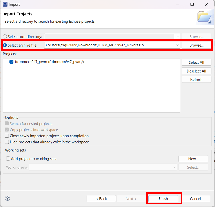
In the next popup window, select **"Select archive file"** and browse to the downloaded project `.zip` file. Then press **"Finish"**.
---
### Build the Project
Now you can build the imported project. Select the project in the Project Explorer and click the **"Build"** icon or use the Quickstart Panel.
The project should compile without errors. If you encounter any issues, make sure:
- The SDK for MCXN947 is properly installed
- All project files were imported correctly
---
### Download and Run
Connect your FRDM-MCXN947 board via the **J17 MCU-LINK** port and follow the same steps as in the LED Blinky demo:
1. Click **"Debug"** to download the application
2. Select **MCU-LINK CMSIS-DAP** as the debug probe
3. Click **"Run"** to start the application
**Congratulations!** You have successfully imported and run the line follower project!
---
---
## Step 4: Reading Line Sensors
### Overview
The line follower robot uses 8 infrared reflective sensors (S10-S17) connected to GPIO pins. These sensors detect the line on the track by measuring the difference in reflectivity between the line and the background surface.
The sensors are connected through the comparators on the shield (U4-U7 LM339), which convert the analog sensor output to digital signals (0 or 1).
**Note:** The GPIO pins are already configured in the provided project. You don't need to configure them manually.
---
### Sensor Reading Functions
The project provides 8 inline functions to read each sensor individually. Each function uses the SDK's `GPIO_PinRead()` to read the current state of the sensor pin.
#### Available Sensor Functions
```c
static inline uint8_t raw_S10(void) {
return GPIO_PinRead(BOARD_INITPINS_S10_GPIO, BOARD_INITPINS_S10_GPIO_PIN);
}
static inline uint8_t raw_S11(void) {
return GPIO_PinRead(BOARD_INITPINS_S11_GPIO, BOARD_INITPINS_S11_GPIO_PIN);
}
static inline uint8_t raw_S12(void) {
return GPIO_PinRead(BOARD_INITPINS_S12_GPIO, BOARD_INITPINS_S12_GPIO_PIN);
}
static inline uint8_t raw_S13(void) {
return GPIO_PinRead(BOARD_INITPINS_S13_GPIO, BOARD_INITPINS_S13_GPIO_PIN);
}
static inline uint8_t raw_S14(void) {
return GPIO_PinRead(BOARD_INITPINS_S14_GPIO, BOARD_INITPINS_S14_GPIO_PIN);
}
static inline uint8_t raw_S15(void) {
return GPIO_PinRead(BOARD_INITPINS_S15_GPIO, BOARD_INITPINS_S15_GPIO_PIN);
}
static inline uint8_t raw_S16(void) {
return GPIO_PinRead(BOARD_INITPINS_S16_GPIO, BOARD_INITPINS_S16_GPIO_PIN);
}
static inline uint8_t raw_S17(void) {
return GPIO_PinRead(BOARD_INITPINS_S17_GPIO, BOARD_INITPINS_S17_GPIO_PIN);
}
```
#### How They Work
Each function:
- **Reads** the digital state of one sensor GPIO pin
- **Returns** `0` or `1` depending on whether the sensor detects the line
- Uses **macros** generated by the pin configuration (`BOARD_INITPINS_Sx_GPIO` and `BOARD_INITPINS_Sx_GPIO_PIN`)
The return value depends on your sensor configuration:
- **Active HIGH:** Returns `1` when line is detected (sensor over black line)
- **Active LOW:** Returns `0` when line is detected (sensor over black line)
#### Sensor Array Layout
The 8 sensors are physically arranged in a line across the front of the robot:
```
[S10] [S11] [S12] [S13] [S14] [S15] [S16] [S17]
Left ← → Right
```
**Important:** Verify the physical orientation of your sensor array. If S10 is on the right side instead of left, you'll need to account for this in your line following algorithm.
---
### Using the Sensor Functions
To use these functions in your line following algorithm, simply call them to get the current state of each sensor:
**Reading a single sensor:**
```c
uint8_t center_left = raw_S13(); // Read center-left sensor
if (center_left == 1) {
// Line detected by S13
}
```
**Reading all sensors:**
```c
uint8_t s10 = raw_S10();
uint8_t s11 = raw_S11();
uint8_t s12 = raw_S12();
uint8_t s13 = raw_S13();
uint8_t s14 = raw_S14();
uint8_t s15 = raw_S15();
uint8_t s16 = raw_S16();
uint8_t s17 = raw_S17();
```
**Creating a sensor reading function:**
You can create a function that combines all 8 sensor readings into a single byte where each bit represents one sensor:
```c
uint8_t read_sensors(void)
{
uint8_t sensors = 0;
if (raw_S10()) sensors |= (1 << 0);
if (raw_S11()) sensors |= (1 << 1);
if (raw_S12()) sensors |= (1 << 2);
if (raw_S13()) sensors |= (1 << 3);
if (raw_S14()) sensors |= (1 << 4);
if (raw_S15()) sensors |= (1 << 5);
if (raw_S16()) sensors |= (1 << 6);
if (raw_S17()) sensors |= (1 << 7);
return sensors;
}
```
This compact representation makes it easy to check multiple sensors at once or store sensor history. The returned byte contains: `0bS17_S16_S15_S14_S13_S12_S11_S10`
---
## Step 5: Motor Control
### Overview
The line follower uses two DC motors controlled by DRV8833 dual H-bridge motor drivers (U2 and U3 on the shield). The motors are controlled using:
- **PWM signals** for speed control (generated by CTIMER)
- **GPIO pins** for direction control (IN1, IN2 for each motor)
**Note:** The motor driver and PWM are already configured in the provided project. You don't need to configure them manually.
---
### Motor Control Function
The project provides the `HbridgeSpeed()` function to control both motors simultaneously.
#### Function Signature
```c
void HbridgeSpeed(hbridge_t *hbridge, int16_t speed1, int16_t speed2);
```
#### Parameters
- **`hbridge`**: Pointer to the H-bridge configuration structure (use `&g_hbridge`)
- **`speed1`**: Speed for motor 1 (range: -100 to +100)
- **Positive values** = forward direction
- **Negative values** = reverse direction
- **Zero** = motor stopped
- **`speed2`**: Speed for motor 2 (range: -100 to +100)
- Same behavior as speed1
#### How It Works
The function:
1. **Converts** the speed value (-100 to +100) to a PWM duty cycle (0% to 100%)
2. **Sets** the motor direction using GPIO pins:
- Forward: IN1=HIGH, IN2=LOW
- Reverse: IN1=LOW, IN2=HIGH
- Stop: IN1=LOW, IN2=LOW
3. **Updates** the CTIMER PWM duty cycle to control motor speed
The absolute value of the speed determines how fast the motor spins, while the sign determines the direction.
---
### Motor Brake Function
The project also provides the `HbridgeBrake()` function to actively brake both motors.
#### Function Signature
```c
void HbridgeBrake(hbridge_t *hbridge);
```
#### Parameters
- **`hbridge`**: Pointer to the H-bridge configuration structure (use `&g_hbridge`)
#### How It Works
The brake function:
1. **Sets both motor direction pins HIGH** (IN1=HIGH, IN2=HIGH)
2. **Creates a short circuit** across the motor terminals
3. **Actively resists** motor rotation, providing quick stopping
#### Difference Between Brake and Stop
**Braking (`HbridgeBrake()`):**
- Sets IN1=HIGH, IN2=HIGH
- Motor terminals are shorted together
- Motor actively resists rotation (regenerative braking)
- **Faster stopping** - robot stops quickly
- Higher current draw during braking
**Stopping (`HbridgeSpeed(&g_hbridge, 0, 0)`):**
- Sets IN1=LOW, IN2=LOW
- Motor terminals are disconnected
- Motor coasts to a stop
- **Slower stopping** - robot gradually slows down
- No additional current draw
#### Using the Brake Function
**Emergency stop:**
```c
HbridgeBrake(&g_hbridge); // Actively brake both motors
```
**Quick stop before direction change:**
```c
HbridgeSpeed(&g_hbridge, 50, 50); // Moving forward
// Need to reverse quickly
HbridgeBrake(&g_hbridge); // Brake first
delay_ms(100); // Wait for motors to stop
HbridgeSpeed(&g_hbridge, -50, -50); // Now reverse
```
**Stopping at a line intersection:**
```c
if (all_sensors_detect_line) {
HbridgeBrake(&g_hbridge); // Quick stop at intersection
}
```
#### When to Use Brake vs Stop
**Use `HbridgeBrake()` when:**
- You need to stop quickly (emergency stop, obstacle detected)
- Stopping at precise positions (intersections, finish line)
- Changing direction rapidly
- Maximum deceleration is required
**Use `HbridgeSpeed(&g_hbridge, 0, 0)` when:**
- Gradual stopping is acceptable
- Conserving power
- Normal end of operation
- Smoother motion is desired
#### Important Notes
**Current Draw:**
- Braking can draw significant current momentarily
- Don't brake continuously for extended periods
- Release brake after robot has stopped
**Mechanical Stress:**
- Frequent hard braking can stress the drivetrain
- Use appropriate braking force for your application
- Consider motor and gearbox limitations
---
### Motor Mapping
In the provided project:
- **Motor 1** (speed1) = Right motor
- **Motor 2** (speed2) = Left motor
This mapping is already configured in the H-bridge initialization. You can use the motors directly without worrying about the physical wiring.
---
### Using the Motor Control Function
To control the robot's movement, call `HbridgeSpeed()` with the desired speeds for both motors.
**Moving forward:**
```c
HbridgeSpeed(&g_hbridge, 50, 50); // Both motors at 50% speed forward
```
**Turning left (differential drive):**
```c
HbridgeSpeed(&g_hbridge, 70, 30); // Right motor faster, left motor slower
```
**Turning right (differential drive):**
```c
HbridgeSpeed(&g_hbridge, 30, 70); // Left motor faster, right motor slower
```
**Moving backward:**
```c
HbridgeSpeed(&g_hbridge, -50, -50); // Both motors at 50% speed reverse
```
**Stopping:**
```c
HbridgeSpeed(&g_hbridge, 0, 0); // Both motors stopped
```
**Sharp turn (spin in place):**
```c
HbridgeSpeed(&g_hbridge, 50, -50); // Right forward, left reverse = spin left
HbridgeSpeed(&g_hbridge, -50, 50); // Right reverse, left forward = spin right
```
---
### Differential Drive Steering
For line following, you'll use **differential drive** - varying the speed of the left and right motors to steer the robot.
**Basic principle:**
- **Both motors same speed** → Robot goes straight
- **Right motor faster** → Robot turns left
- **Left motor faster** → Robot turns right
- **Speed difference** determines how sharp the turn is
**Typical line following approach:**
1. **Read sensors** to determine line position
2. **Calculate error** (how far off-center the line is)
3. **Adjust motor speeds** based on error:
- If line is **left of center** → slow down left motor, speed up right motor
- If line is **right of center** → slow down right motor, speed up left motor
- If line is **centered** → both motors at same speed
---
### Important Notes
**Speed Range:**
- The valid range is **-100 to +100**
- Values outside this range will be clamped automatically
- Start with lower speeds (30-60) for testing and gradually increase
**Motor Response:**
- Motors may not respond to very low speed values (< 20)
- Each motor may have slightly different characteristics
- You may need to calibrate speeds for straight-line driving
**Control Loop Frequency:**
- Call `HbridgeSpeed()` regularly in your main loop
- Typical frequency: 100-200 Hz (every 5-10 ms)
- Too slow → jerky movement
- Too fast → unnecessary CPU usage
---
### Your Task: Implement Line Following
Now that you have:
- **Sensor reading functions** (`raw_S10()` through `raw_S17()`)
- **Motor control function** (`HbridgeSpeed()`)
You need to implement the line following algorithm that:
1. Reads the sensor array
2. Determines the line position
3. Calculates appropriate motor speeds
4. Calls `HbridgeSpeed()` to steer the robot
**Suggested approach:**
- Start with a simple algorithm (e.g., if-else based on sensor patterns)
- Test on a simple track
- Gradually improve with more sophisticated control (e.g., PID controller)
- Tune parameters for speed and accuracy
**Good luck with your line follower!**
---
[← Back to Main](../tutorial.md)