shield-components.md
NXPCUP-Shield-FRDM-MCXN947 Electronic Components
← Back to Main | ← Component List
Electronic Components List
| Reference | Quantity | Image | Description |
|---|---|---|---|
| C1-C5 | 5 | 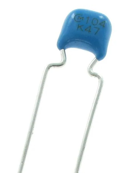 |
Ceramic capacitors 100nF |
| D1 | 1 | 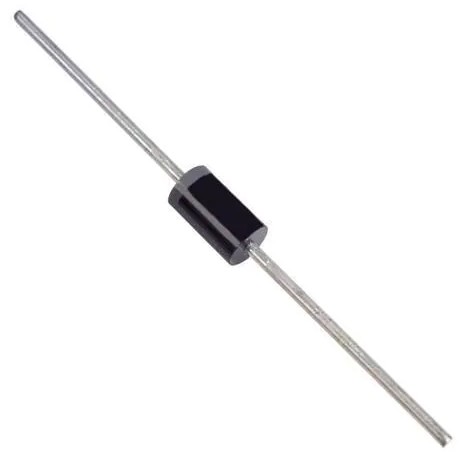 |
Schottky diode 1N5822 |
| J1 | 1 | 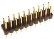 |
2x10 pin header connector |
| J2, J5 | 2 | 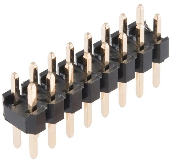 |
2x8 pin header connectors |
| J6 | 1 | 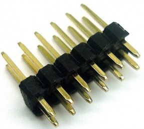 |
2x6 pin header connector |
| J7-J9 | 3 | 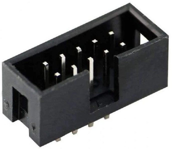 |
2x5 pin header connectors |
| J10 | 1 | 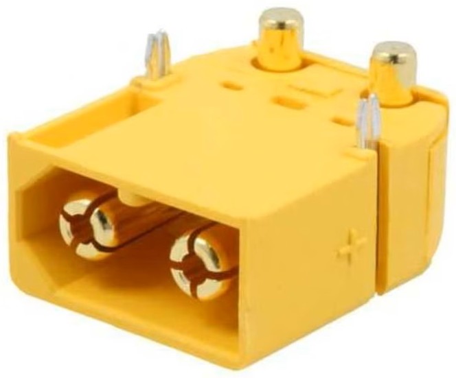 |
XT60 power connector |
| J11, J12 | 2 | 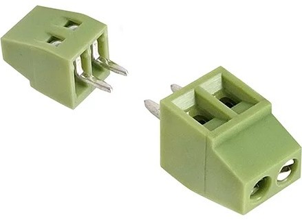 |
2-pin screw terminals |
| J13, J17 | 2 | 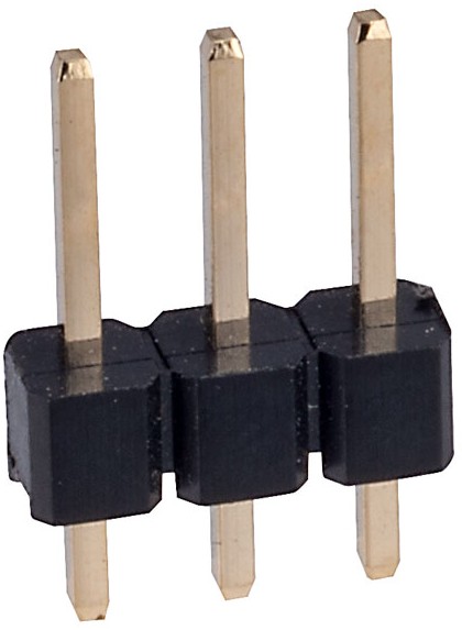 |
3-pin connectors |
| J14, J15 | 2 | 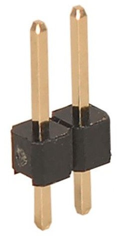 |
2-pin connectors |
| Jumper | 1 | 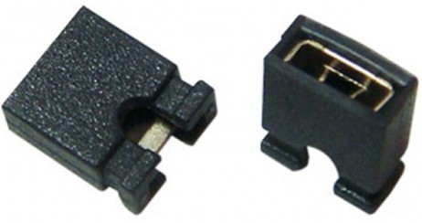 |
Jumper |
| R1-R20 | 20 |  |
Resistors 10kΩ |
| RV1 | 1 | 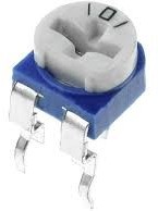 |
Potentiometer 10kΩ |
| S1 | 1 | 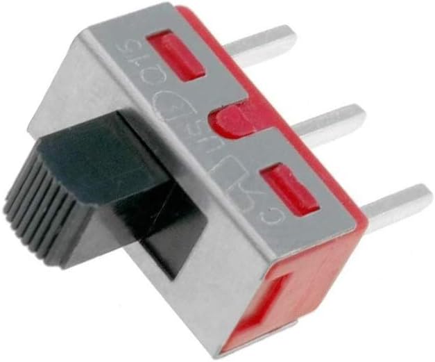 |
Switch |
| SW1 | 1 | 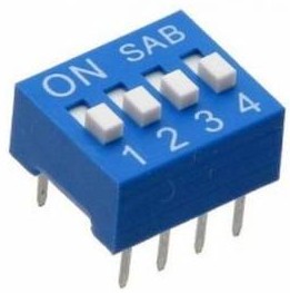 |
4-position DIP switch |
| U1 | 1 | 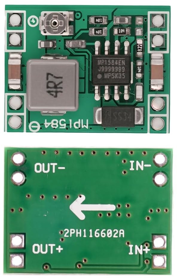 |
DC-DC step-down converter MP1584EN |
| U2, U3 | 2 | 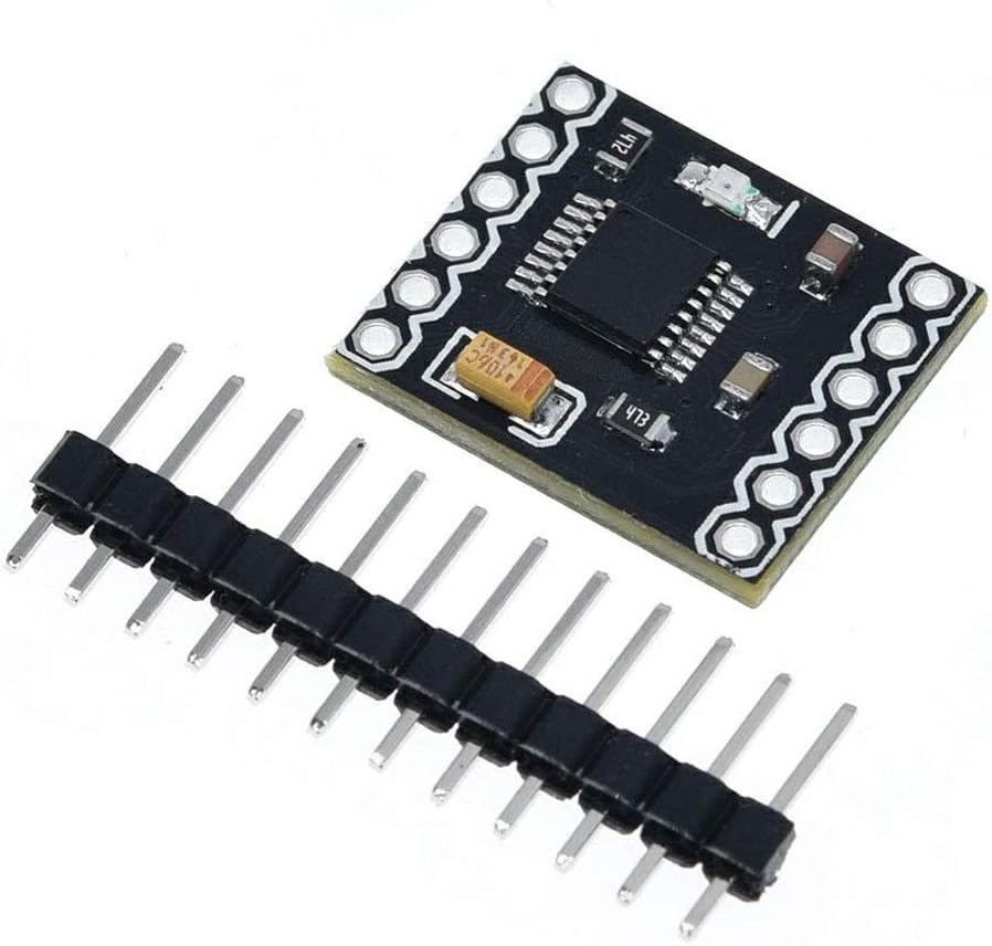 |
Dual H-bridge motor drivers DRV8833 |
| U4-U7 | 4 | 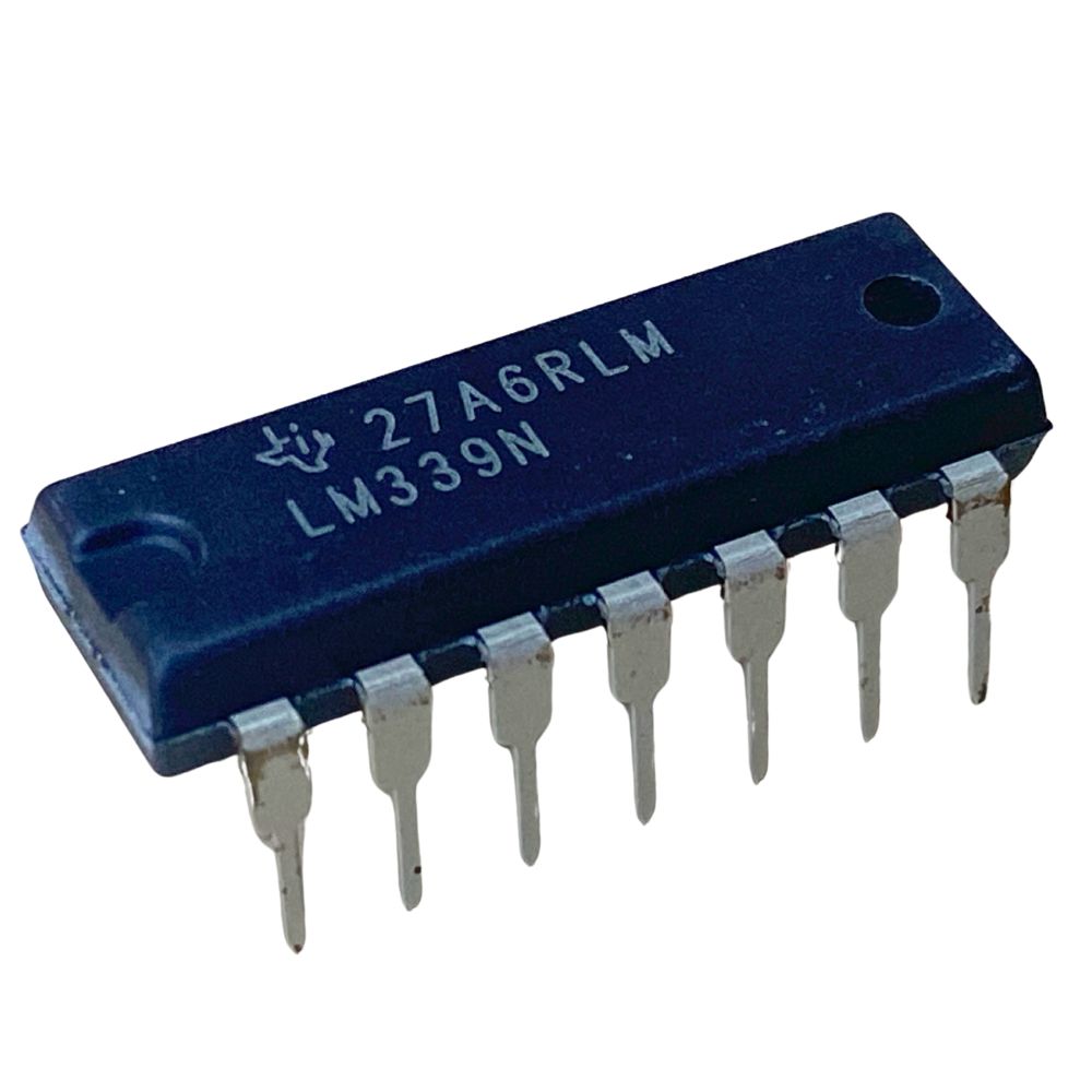 |
Quad comparators LM339 |
| U4-U7 | 4 | 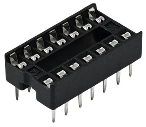 |
IC socket 14-pin DS1009-14AT |
Component Categories
Passive Components
- Resistors (R1-R20): 20x 10kΩ metal film resistors for pull-up configurations
- Capacitors (C1-C5): 5x 100nF ceramic capacitors for power supply filtering and decoupling
- Potentiometer (RV1): 1x 10kΩ adjustable resistor for sensor threshold adjustment
Active Components
- Diode (D1): 1x Schottky diode 1N5822 for reverse polarity protection
- Comparators (U4-U7): 4x LM339 quad comparators for line sensor signal processing
- Motor Drivers (U2, U3): 2x DRV8833 dual H-bridge drivers for motor control
- DC-DC Converter (U1): 1x MP1584EN step-down converter for voltage regulation
Connectors
- Header Connectors (J1, J2, J5, J6): For interfacing with FRDM-MCXN947 board
- JTAG Connectors (J7-J9): For camera and line sensor array connections
- Power Connector (J10): XT60 connector for battery connection
- Motor Terminals (J11, J12): Screw terminals for motor connections
- Auxiliary Connectors (J13, J17): For additional peripherals
- Power selection jumpers (J14, J15): 2-pin connectors for selecting camera power source (connected to J9)
Switches & Controls
- Power Switch (S1): Main power on/off switch
- DIP Switch (SW1): 4-position switch for configuration settings (keep position 3 in ON state, do not use)
- Jumper: For configuration selection
Component Notes
Important Polarized Components
⚠️ Pay special attention to polarity:
- D1 (Diode): Band marking indicates cathode
- U4-U7 (LM339): Notch or dot indicates pin 1
- J10 (XT60): Red = positive (+), Black = negative (-)
IC Sockets
The IC sockets for U4-U7 allow easy replacement of the LM339 comparators if needed. Always insert ICs with correct orientation (notch alignment).
Module Components
U1, U2, and U3 are pre-assembled modules that will be soldered or mounted onto the shield PCB.
Next: Shield Assembly Guide →